MHC-V41D
9
SECTION 2
DISASSEMBLY
• This set can be disassembled in the order shown below.
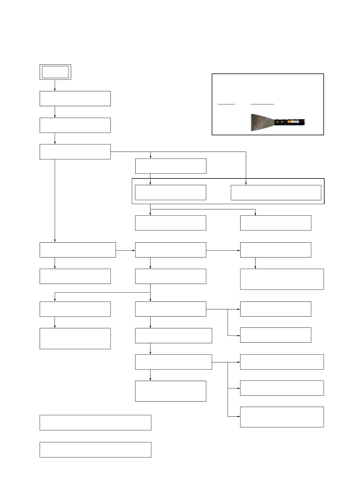
2-1. DISASSEMBLY FLOW
SET
2-2. SIDE PANEL
(Page 10)
2-3. TOP PANEL BLOCK-1
(Page 11)
2-27. CHASSIS BLOCK SERVICE POSITION
(Page 33)
2-28. TOP PANEL BLOCK SERVICE POSITION
(Page 33)
2-4. TOP PANEL BLOCK-2
(Page 12)
2-5. LOADING PANEL BLOCK
(Page 13)
2-6. LOADING PANEL
(Page 14)
2-11. PARTY LED BOARD
(Page 18)
2-12. DC FAN,
REAR PANEL
(Page 19)
2-22. FRONT PANEL BLOCK-2
(Page 28)
2-23. SW LED BOARD,
IR BOARD
(Page 29)
2-14. SMPS BOARD
(Page 21)
2-10. REAR PANEL BLOCK
(Page 18)
2-13. CHASSIS BLOCK
(Page 20)
2-15. MOTHER BOARD
(Page 22)
2-24. LOUDSPEAKER (TWEETER)
(Page 30)
2-26. LOUDSPEAKER
(SUBWOOFER)
(Page 32)
2-25. LOUDSPEAKER (MIDRANGE)
(Page 31)
2-7. CDM BLOCK
(Page 15)
2-9. OPTICAL PICK-UP BLOCK
(CMS-S76RFS7G)
(Page 17)
2-8. FFC HOLDER
(Page 16)
2-21. FRONT PANEL BLOCK-1
(Page 27)
2-16. MIC BOARD
(Page 23)
2-18. ELECTRET CAP MICROPHONE
(Page 25)
2-17. PANEL BOARD
(Page 24)
2-19. NFC BOARD
(Page 25)
2-20. GESTURE BOARD
(Page 26)
JIG
When disassembling the unit, use the following
jig for speaker removal.
Part No. Description
J-2501-238-A JIG FOR SPEAKER REMOVAL

 Loading...