MHC-V41D
22
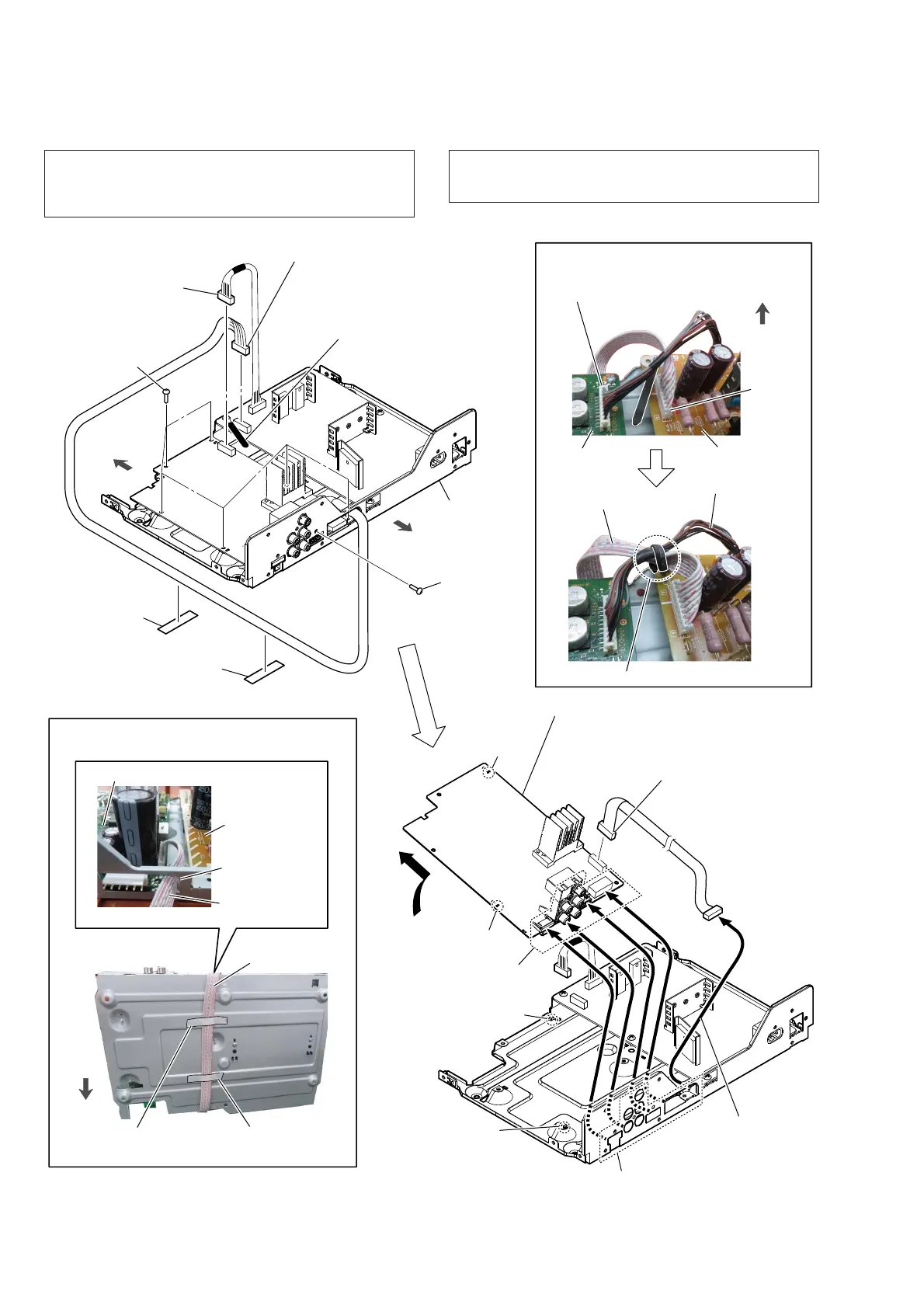
2-15. MOTHER BOARD
front side
rear side
< Fig. N >
– Bottom view –
< Fig. M >
:LUHVHWWLQJ
SMPS board cable
MOTHER
board
SMPS board
CN6500
MOTHER board cable
coating clip
CN001
front side
– Top view –
2 SMPS board cable
connector (CN001)
(See Note 1)
1 Remove the two cables
from the coating clip.
(See Fig. M)
3 MOTHER board cable
connector (CN6500)
(See Note 1)
chassis block
6 six screws
(BVTP3 u 8)
4
filament tape
(sub material)
(See Fig. N)
5 screw
(P3 u 8)
4
filament tape
(sub material)
(See Fig. N)
7
8 Draw the connector
and jack out of the
hole in chassis.
9 Draw the MOTHER
board cable out of
the hole in chassis.
(See Fig. N)
hole
rib
hole
rib
qa MOTHER board (See Note 2)
Note 3:
When installing the MOTHER board,
align the two ribs and two holes.
0 MOTHER board cable
connector (CN2007)
hole
MOTHER board
MOTHER board
cable
:LUHVHWWLQJ
–5HDUYLHZ–
filament tape
(sub material)
filament tape
(sub material)
SMPS board
MOTHER board
cable
hole
front side
Note 1: Make sure perform discharge processing before removing the
MOTHER board. For the discharge processing method, refer
to “CAPACITOR ELECTRICAL DISCHARGE PROCESS-
ING” on page 5.
Note 2: When the MOTHER board is replaced, refer to “DESTI-
NATION SETTING METHOD” and “NFC OPERATION
CHECKING METHOD” on page 6.

 Loading...