359Simple P/P Software
Chapter 10 Special Functions
Assignment of signals to output connectors
Note
The output connector OUT24 cannot be used.
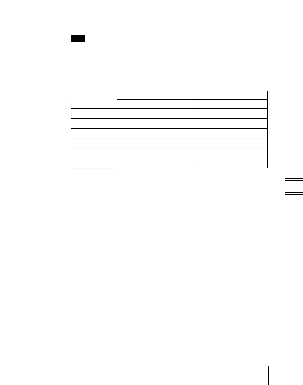
Connectors to which the P/P row output signal assignment is fixed
The assignment of the following signals to output connectors OUT17 to OUT2
2 is fixed.
Except for Preset, you can select these signals on the AUX bus for output.
a) Depends on the setting in the Engineering Setup >Switcher >Config >M/E Output Assign menu.
Logical assignment of the physical PGM/PST
In the Engineering Setup >Switcher >Config >Logical M/E Assign menu, it is
not possible to assign the physical PGM/PST as a logical PGM/PST.
In the <Logical M/E to Physical P/P> group, you can select from M/E-1, M/E-
2, and M/E-3.
Configuration of the switcher bank outputs
If Multi Program mode is selected in setup (M/E Config in the Switcher
>Config menu), then for Bkgd in the PGM Config menu, it is only possible to
select Clean.
Assigning a simple P/P re-entry signal to a primary input
When returning output from a simple P/P to a primary input, use the following
procedure to set where the signal returns.
1
In the Switcher >Output menu, select [Output Assign] and press [Simple
P/P Re-Entry Assign].
The Simple P/P Re-Entry Assign menu appears.
Output
connector
Fixed assigned outputs
Standard mode Multi-program mode
OUT17 Program
P/P OUT1
a)
OUT18 Program
P/P OUT1
a)
OUT19 Preview
P/P OUT2
a)
OUT20 Clean
P/P OUT3
a)
OUT21 Key preview
P/P OUT4
a)
OUT22 Preset Preset