25
Names and Functions of Parts
Chapter 1 Overview
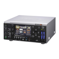
b AUDIO INPUT CH-1 and CH-2
(channels 1 and 2) connectors (phono
jacks)
Input analog audio signals to the CH-1 and
CH-2 connectors. Set the input level with
the AUDIO INPUT LEVEL switch to –10,
–2, or +4 dBu.
c AUDIO OUTPUT CH-1/3 and CH-2/
4 (channels 1 and 3, channels 2 and 4)
connectors (phono jacks)
Output analog audio signals from the CH-1/
3 and CH-2/4 connectors.
Output channels can be selected by
changing the “Monitor CH” setting (see
page 88) and the “Output CH” setting (see
page 88) of the AUDIO SET menu.
In recording or E-E mode, audio signals of
channels 1 and 2 are output. (Channels 3
and 4 can be selected when 4-channel
material is played back.)
d COMPOSITE connector (BNC type)
Outputs down-converted SD analog
composite video signals.
Setting “CMPST/ S Out Display” (see page
89) of the VIDEO SET menu to “On”
superimposes the same text information as
that displayed on the LCD display on the
output signals from this connector.
e S-VIDEO connector (mini-DIN 4-
pin)
Outputs Y/C separated signals.
Setting “CMPST/ S Out Display” (see page
89) of the VIDEO SET menu to “On”
superimposes the same text information as
that displayed on the LCD display on the
output signals from this connector.
f COMPONENT connectors (BNC
type)
Output HD analog component signals or
down-converted SD analog component
signals from the Y, Pb/B–Y, and Pr/R–Y
connectors. Select the video format of the
output signals with “HDMI/CMPNT/SDI
Out SEL” (see page 88) of the VIDEO SET
menu.
Setting “HDMI/CMPNT/SDI Out DISP”
(see page 89) of the VIDEO SET menu to
“On” superimposes the same text
information as that displayed on the LCD
display on the output signals from this
connector.
The output format is fixed to 480i (576i)
when the “i.LINK I/O Select” setting (see
page 90) of the VIDEO SET menu is
“DVCAM”.
g DC IN (DC power source input)
connector (3-pin, Type 4)
Plugs the DC power cord to connect the
supplied MPA-AC1 AC Adaptor.
h HDMI connector (Type A 19-pin)
Select the video format of the output signals
with “HDMI/CMPNT/SDI Out SEL” (see
page 88) of the VIDEO SET menu.
Setting “HDMI/CMPNT/SDI Out DISP”
(see page 89) of the VIDEO SET menu to
“On” superimposes the same text
information as that displayed on the LCD
display on the output signals from this
connector.
The output format is fixed to 480i (576i)
when the “i.LINK I/O Select” setting (see
page 90) of the VIDEO SET menu is
“DVCAM”.
Note
Note
Note