48
Recording
Chapter 3 Recording and Playback
It is not possible to change the input
signal during recording. If the VIDEO
INPUT switch position is changed, the
setting is not enabled until the
recording stops with the STOP button
pressed.
3 When recording audio signals input to
the AUDIO INPUT CH-1 and CH-2
connectors, set the AUDIO INPUT
LEVEL switch as follows.
When audio signals output from an
XLR connector: +4 or –2
When audio signals output from a
phono jack: –10
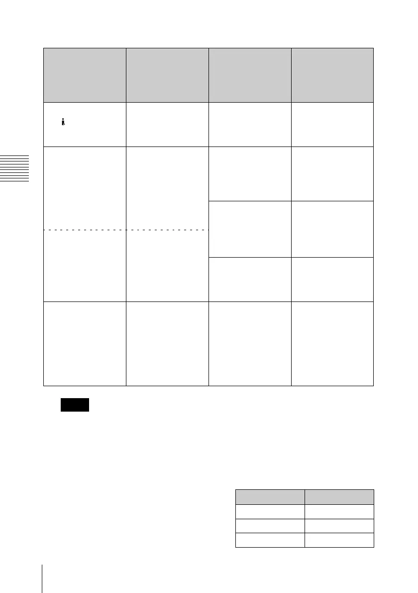
The following table shows the relation
between the switch position and
maximum audio level available.
Video signal to
record
VIDEO INPUT
switch position
(input signal
indication on the
monitor screen)
Audio signal to
record
AUDIO INPUT
switch position
HDV signals input to
the HDV/DV
connector
i.LINK (i.LINK in) 2-channel digital
audio signals
embedded in the
input HDV signals
—
HDSDI signals input
to the HD SDI
INPUT connector
HD SDI (HDSDI in) Analog audio
signals input to the
AUDIO INPUT CH-1
and CH-2
connectors
ANALOG
Channels 1 and 2 of
digital audio signals
embedded in the
input HDSDI signals
HD SDI CH-1/2
Internal test signal
(100% full color bar)
SG (Internal SG)
Channels 3 and 4 of
digital audio signals
embedded in the
input HDSDI signals
HD SDI CH-3/4
Internal test signal
(100% full color bar)
SG (Internal SG) 1 kHz reference
audio signal
Regardless of the
AUDIO INPUT
switch position, set
“1kHz Tone” in the
“Audio Input” setting
of the AUDIO SET
menu to “On” (see
page 87).
Note
Position Audio level
–10 +10 dBu
–2 +18 dBu
+4 +24 dBu