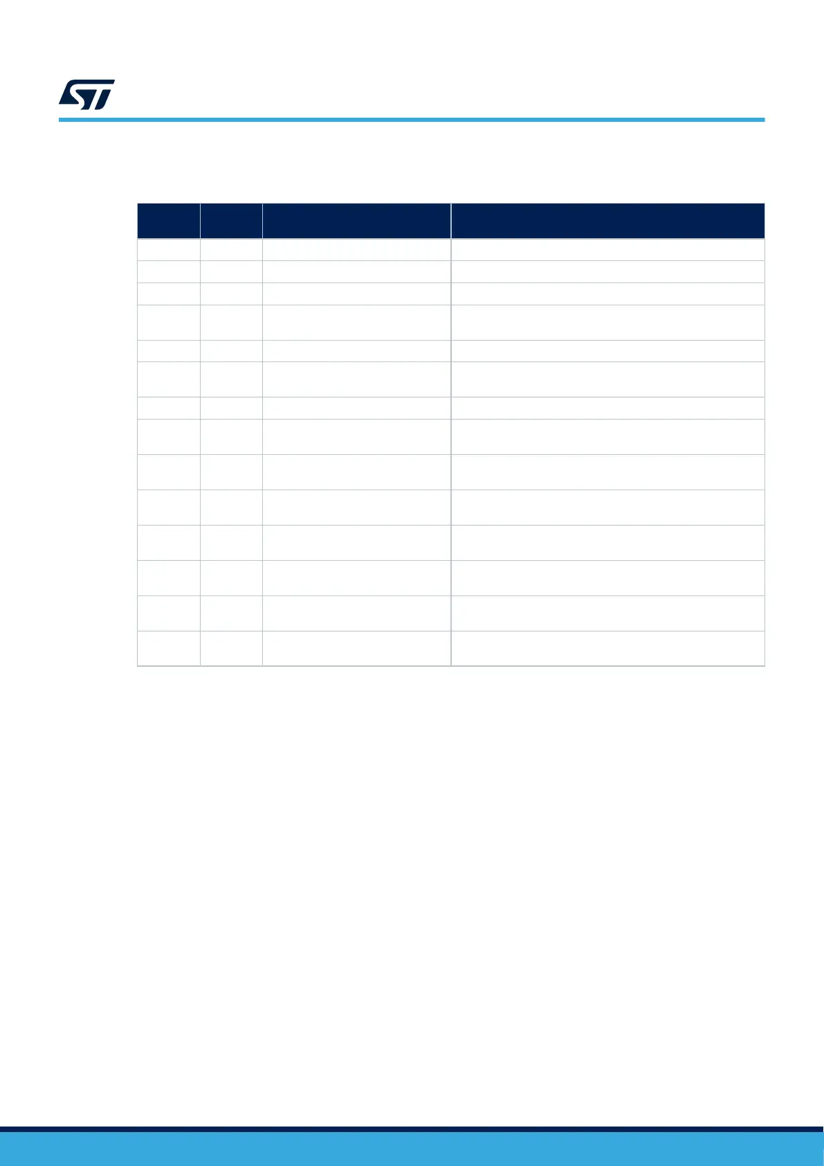
Table 4 describes the STDC14 / MIPI10 connector pinout (CN12).
Table 4. STDC14 / MIPI10 debug connector pinout (CN12)
MIPI10
pin
STDC14
pin
CN12 Designation
- 1 NC Reserved
- 2 NC Reserved
1 3 T_VCC Target VCC
2 4 T_SWDIO
Target SWDIO using SWD protocol or target JTMS (T_JTMS)
using JTAG protocol
3 5 GND Ground
4 6 T_SWCLK
Target SWCLK using SWD protocol or target JCLK (T_JCLK)
using JTAG protocol
5 7 GND Ground
6 8 T_SWO
Target SWO using SWD protocol or target JTDO (T_JTMS)
using JTAG protocol
7 9 T_JRCLK
Not used by SWD protocol, Target JRCLK (T_JRCLK) using
JTAG protocol, only for specific use
8 10 T_JTDI
Not used by SWD protocol, Target JTDI (T_JTDI) using JTAG
protocol, only for external tools
9 11 GNDDetect
GND detect for plug indicator, used on SWD and JTAG
neither
10 12 T_NRST
Target NRST using SWD protocol or target JTMS (T_JTMS)
using JTAG protocol
- 13 T_VCP_RX
Target RX used for VCP (must be UART dedicated to
Bootloader)
- 14 T_VCP_TX
Target TX used for VCP (must be UART dedicated to
Bootloader)
UM3143
Using an external debug tool to program and debug the on-board STM32
UM3143 - Rev 1
page 13/53

 Loading...


