14 Board functions
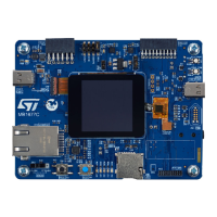
14.1 TFT LCD 240 × 240 pixels and capacitive touch panel
The STM32H573I-DK board includes a 1.54-inch TFT LCD with 240 × 240 pixel resolution (which is driven by the
on-board display controller), white LED backlight, and capacitive touch panel. Each pixel can display 262 000
different colors.
No external RAM is needed. Display data are stored in the on-chip display data RAM of 240 × 320 × 18 bits. It
performs display data RAM read/write operations with no external operation clock to minimize power
consumption.
The TFT LCD is covered with a capacitive touch panel.
The LCD_BL_CTRL signal (PI3) allows the backlight to be switched ON/OFF through the LED backlight driver IC.
14.2 USB full speed
The STM32H573I-DK board supports USB full-speed communications via the user USB Type-C
®
connector
CN17.
The USB Type-C
®
connector can also be used to power the STM32H573I-DK board with a 5 V DC supply
voltage, at a current up to 3 A.
The on-board companion chip (U30) provides overvoltage protection on CC1 and CC2 pins against short-to-V
BUS
and functionalities to comply with the USB-C
®
Power Delivery Specifications.
The LD7 USB V
BUS
LED serves as an indicator for V
BUS
voltage detection and is ON when V
BUS
is present on
the USB Type-C
®
connector (CN17).
14.2.1 Device and Host modes
When a USB Host connection to the CN17 USB Type-C
®
connector of the STM32H573I-DK Discovery kit is
detected, the board starts behaving as a USB Device. Depending on the powering capability of the USB Host, the
board can take power from the V
BUS
terminal of CN17. In the board schematic, the corresponding power voltage
line is called 5V_UCPD.
Note: 1. In Sink mode, the 5 V power source selector (JP4) must be set on the ‘USB-PD: position [3-4].
2. In Source mode, the 5 V power source selector (JP4) must be set on ‘STLK: position [1-2].
14.2.2 Configuration channel I/Os
The UCPD_CCx signals are connected to the associated CCx line of the USB Type-C
®
connector through the on-
board USB port protection. These lines are used for the configuration channel lines (CCx) to select the USB Type-
C
®
current mode.
14.2.3 V
BUS
fault detection
The UCPD_FLT signal is provided by the ST USB Type-C
®
port protection. It is used as fault reporting to the
STM32H573II MCU after a bad V
BUS
level detection. By design, the STM32H573I-DK V
BUS
protection is set to
6 V maximum with the RSENSE. The USB port protection is driven by an I
2
C bus. The base I
2
C-bus address is
0b 0110 100x.
The hardware configuration for the USB FS interface is shown in Table 11.
Table 11. USB Type-C
®
FS power delivery configuration
I/Os
Configuration
PG0 EN (UCPD_PWR)
PF13 IANA (IBUS_SENSE)
PB13 CC1 (UCPD_CC1)
PB14 CC2 (UCPD_CC2)
PG1 FLGn (UCPD_FLT)
UM3143
Board functions
UM3143 - Rev 1
page 23/53

 Loading...