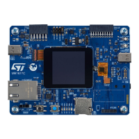
14.10.1 MIPI10 connector (CN12)
The STM32H573I-DK board includes a MIPI10 connector (CN12) for SWD/JTAG debugging/programming
capabilities.
Note: The MIPI10 connector supports 1.8 V or 3.3 V for target reference voltage.
14.10.2 MIPI20 connector (CN18)
The STM32H573I-DK board also includes a MIPI20 connector (CN18) for debug features (SWD or JTAG) as well
as
ETM instruction trace.
Important: Always make sure to set the JP1 jumper before connecting any debugging probe to CN18 or CN12. Indeed,
before connecting an external debugger to CN18 or CN12, it is mandatory to isolate the output I/Os (SWD and
UART_VCP) from STLINK-V3EC.
Table 15 explains the JP1 jumper settings.
Table 15. JP1 jumper settings
Jumper Definition Settings Comment
JP1 Debugger selection
ON [1-2]
An external debugger on MIPI20/MIPI10 connector (CN18/
CN12) can be used. The level shifter (U26) is in High
Impedance (HZ).
The STLINK-V3EC no longer drives the embedded STM32.
OFF
The embedded STLINK-V3EC is selected (default
configuration).
Note: The MIPI20 trace connector supports 1.8 V or 3.3 V for target reference voltage.
14.11
Buttons and LEDs
The black button B2 connected to NRST is the reset button and is used to reset the STM32H573IIK3Q
microcontroller.
When the button B2 is pressed, the logic state is LOW, otherwise the logic state is HIGH.
The blue button B1 connected to PC13 is the user button.
When the button B1 is pressed, the logic state is HIGH, otherwise the logic state is LOW.
Four LEDs LD1-LD4 with colors green, orange, red, and blue respectively (refer to Figure 4), are available for the
user. To light a LED, a low-logic state “1” should be written in the corresponding GPIO register. Table 16 shows
the assignment of the control ports to the LED indicators.
Table 16. Buttons and LED control port
Reference
Color Name Comment
B2 Black RESET Reset function
B1 Blue USER Wake-up alternate function
LD1 Green USER_LED1 PI9
LD2 Orange USER_LED2 PI8
LD3 Red USER_LED3 PF1
LD4 Blue USER_LED4 PF4
LD5 Green 5V POWER 5 V power supply available
LD6 Green ARDUINO PI1
LD7 Green 5V_USB_LED
V
BUS
available on USB Type-
C
®
user connector
UM3143
Buttons and LEDs
UM3143 - Rev 1
page 27/53

 Loading...