Table 21. Pmod
™
connector CN6 pinout
Pin number Description Pin number Description
1 SPI5_NSS / USART7_CTS (PF6/PF9) 7 INT (PH9)
2 SPI5_MOSI / USART7_TX (PF9/PF7) 8 RESET (PH6)
3 SPI5_MISO / USART7_RX (PF8/PF6) 9 Not connected
4 SPI5_SCK / USART7_RTS (PF7/PF8) 10 Not connected
5 GND 11 GND
6 3V3 12 3V3
Limitation: On the STM32H573I-DK board, SPI5 and UART7 signals are used to control a device connected to
STMod+ or to Pmod
™
. Therefore, when using the Pmod
™
connector, the user must make sure that nothing is
connected on the STMod+ connector.
15.5 TAG connector (CN1)
The TAG connector footprint CN1 is used to connect the STM32H573IIK3Q microcontroller for programming or
debugging the board.
Figure 18. TAG connector CN1
The related pinout for the TAG connector is listed in Table 22.
Table 22. TAG connector CN1 pinout
Pin number
Description Pin number Description
1 VDD (3V3) 10 NRST
2 SWDIO / JTMS (PA13) 9 NJTRST (PB4)
3 GND 8 JTDI (PA15)
4 SWCLK / JTCK (PA14) 7 NC
5 GND 6 TRACESWO / JTDO (PB3)
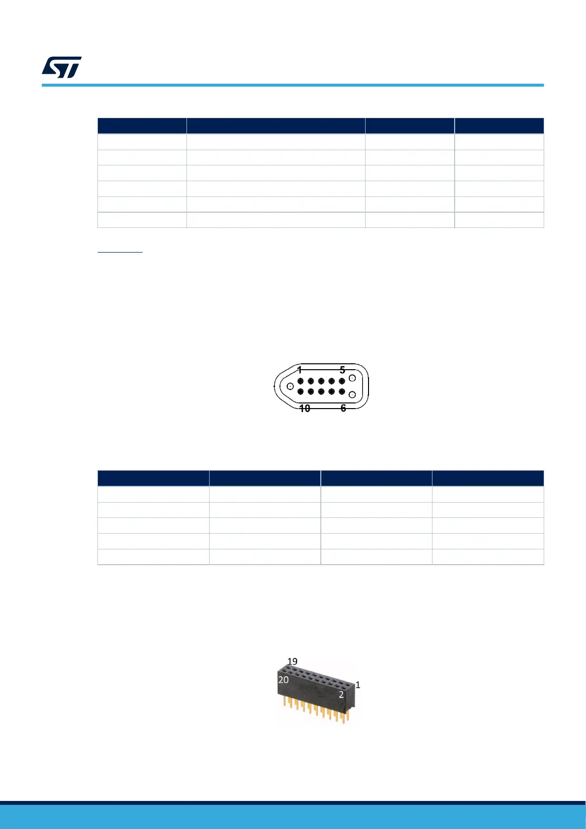
15.6 Audio connector (CN2)
The 2 × 10-male-pin 1.27 mm-pitch audio connector is used for audio MEMS daughterboard expansion using the
PDM interface.
Figure 19. Audio connector CN2
The related pinout for the audio connector is listed in Table 23.
UM3143
TAG connector (CN1)
UM3143 - Rev 1
page 32/53

 Loading...


