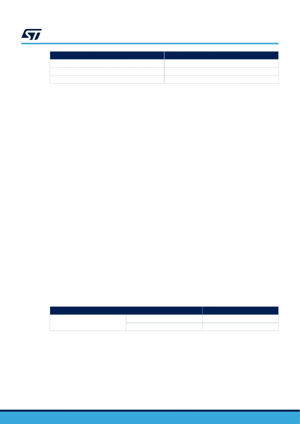
I/Os Configuration
PF14 VBUS_SENSE
PB8 SCL (I2C4_SCL)
PB9 SDA (I2C4_SDA)
14.3 Ethernet
The STM32H573I-DK board supports 10/100-Mbit operating rates for Ethernet communication. The Ethernet
subsystem is provided by the on-board Ethernet transceiver (U11) and the RJ45 (CN8) with integrated Magnetic.
The 25 MHz clock of the Ethernet PHY is sourced from the X3 oscillator, while the PHY RMII_REF_CLK provides
the 50 MHz clock to the STM32H573IIK3Q RMII reference clock pin.
Note: The Ethernet can operate at 1.8 V or 3.3 V.
14.4
microSD
™
card
A slot for a microSD
™
card (CN4), SD 2.0 compliant, is available on the STM32H573I-DK board and is connected
to the SDOI1 interface of the
STM32H573IIK3Q.
The microSD
™
card detection is managed by the uSD_Detect signal.
When a microSD
™
card is inserted in the slot, the uSD_Detect signal level is 0, otherwise it is 1.
Note:
The microSD
™
operates at 3.3 V only. (JP2 must be ON [1-2]).
14.5 Audio
The audio codec used on the STM32H573I-DK is a low-power stereo codec with a headphone amplifier, which is
connected to the STM32H573IIK3Q SAI2 interface. It communicates with the STM32H573IIK3Q microcontroller
via an I
2
C-bus shared with the touch panel of the LCD and the USB-C
®
protection. The I
2
C-bus address of the
audio codec is 0x94.
Several audio connections are available on the STM32H573I-DK board:
• Analog audio output lines of the audio codec are used to drive a headphone connected to the audio jack
connector (CN9) since the analog input of the codec is used as microphone input when a microphone is
connected to the audio jack connector (CN9)
• For microphone-based applications, a MEMS microphone daughterboard can be plugged into the audio
connector CN2. The daughterboard interfaces with the STM32H573IIK3Q via the SAI1 peripheral using a
PDM interface.
14.5.1 Digital MEMS microphone
The STM32H573I-DK Discovery kit also provides one digital MEMS microphone (U20) which is connected to the
MCU's SAI1 interface. The I/O interface is described in Table 12.
Table 12. Digital MEMS microphones I/O interface
Microphone pin
STM32H573IIK3Q I/O
U20
CLK PD11 (PDM_SAI1_CK1)
DOUT PD6 (PDM_SAI1_SD1)
The selection between the on-board digital MEMS microphone and the external digital MEMS microphone
daughterboard plugged into the audio connector (CN2) is made by the U23 SPDT switch. The DETECn signal
(PE0) controls the switch. Table 13 shows the selection between the on-board digital MEMS microphone and the
external digital MEMS microphone daughterboard.
UM3143
Ethernet
UM3143 - Rev 1
page 24/53

 Loading...


