7 Hardware layout and configuration
7.1 Hardware layout
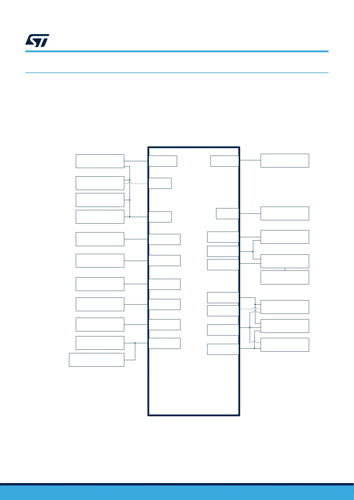
The STM32H573I-DK is designed around the STM32H573IIK3Q microcontroller in a 176-pin BGA package.
Figure 3 illustrates the connection between the STM32H573IIK3Q microcontroller and the peripherals (STLINK-
V3EC, push-buttons, LEDs, Octo‑SPI flash memory, LCD, microSD
™
card, USB, Ethernet, audio codec, MEMS
digital microphones, STMod+/Pmod
™
/ARDUINO
®
connectors).
Figure 3. STM32H573I-DK hardware block diagram
DT71723V1
STM32H573II
UFBGA176
USART1
STLINK-V3EC
TRACE
SWD
Trace connector
TAG connector
SWD connector
32.768 kHz crystal /
25 MHz oscillator
RTC / HSE
USB-C
USB Type-C
®
Sink and Source
Ethernet
RMII
LCD
Audio codec and
amplifier
Stereo jack
(IN / OUT)
ARDUINO
®
connector
STMod+ connector
Pmod™ connector
OCSPI1
GPIO
PWR
SDIO1
SAI1 (PDM)
FMC
I2C4
SAI2
I2C1
UART3
SPI5
UART7
512-Mbit Octo-SPI
flash memory
User LEDs
Power supply
microSD™
connector
MEMS microphone
(on-board)
Audio connector
(5 MEMS microphones)
UM3143
Hardware layout and configuration
UM3143 - Rev 1
page 8/53

 Loading...


