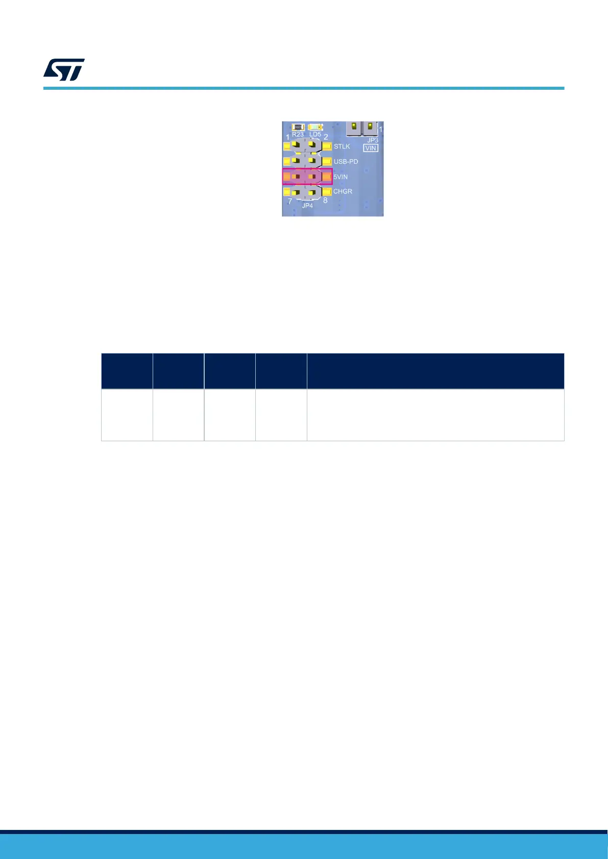
Figure 9. JP4 set on the VIN pin
When using STLINK-V3EC for debug when powering the board with an external power supply from VIN, it is
important to power the board first, before connecting the host PC to
CN10, which requires the following sequence
to be respected:
1. Set the jumper between the pins 5-6 of JP4 “5VIN.”
2. Connect the external power source to pin 1 of CN14.
3. Check that the green LED LD5 is turned ON.
4. Connect the host PC to USB connector CN10.
Table 7. External power source: VIN (7-12 V)
Input
power
name
Connector
pins
Voltage
range
Max.
current
Limitation
VIN CN14 pin 1 7 to 12 V 800 mA
From 7 to 12 V only; and input capability is linked to input voltage:
• 800 mA input current when VIN = 7 V
• 450 mA input current when 7 V < VIN < 9 V
• 250 mA input current when 9 < VIN < 12 V
UM3143
Supplying the board by VIN (7-12 V, 800 mA max.)
UM3143 - Rev 1
page 16/53

 Loading...


