9 Power supply
For powering the STM32H573I-DK kit, there are several options. With this, the user gets the flexibility to choose
the power supply which suits the application most.
The JP4 jumper allows the user to select any of the following power sources:
• STLK: 5 V from STLINK-V3EC USB Type-C
®
connector (CN10)
• USB-PD: 5 V from user USB Type-C
®
connector (CN17)
• 5VIN: 5 V to 12 V from ARDUINO
®
connector (pin 1 of CN14)
• CHGR: 5 V from STLINK-V3EC (CN10) without enumeration.
The green power LED (LD5) indicates the presence of 5 V supply voltage.
9.1
Supplying the board by the STLINK-V3EC USB Type-C
®
connector (default
setting)
To power the STM32H573I-DK in this way, the USB Host (a PC) needs to be connected to the STLINK-V3EC
USB Type-C
®
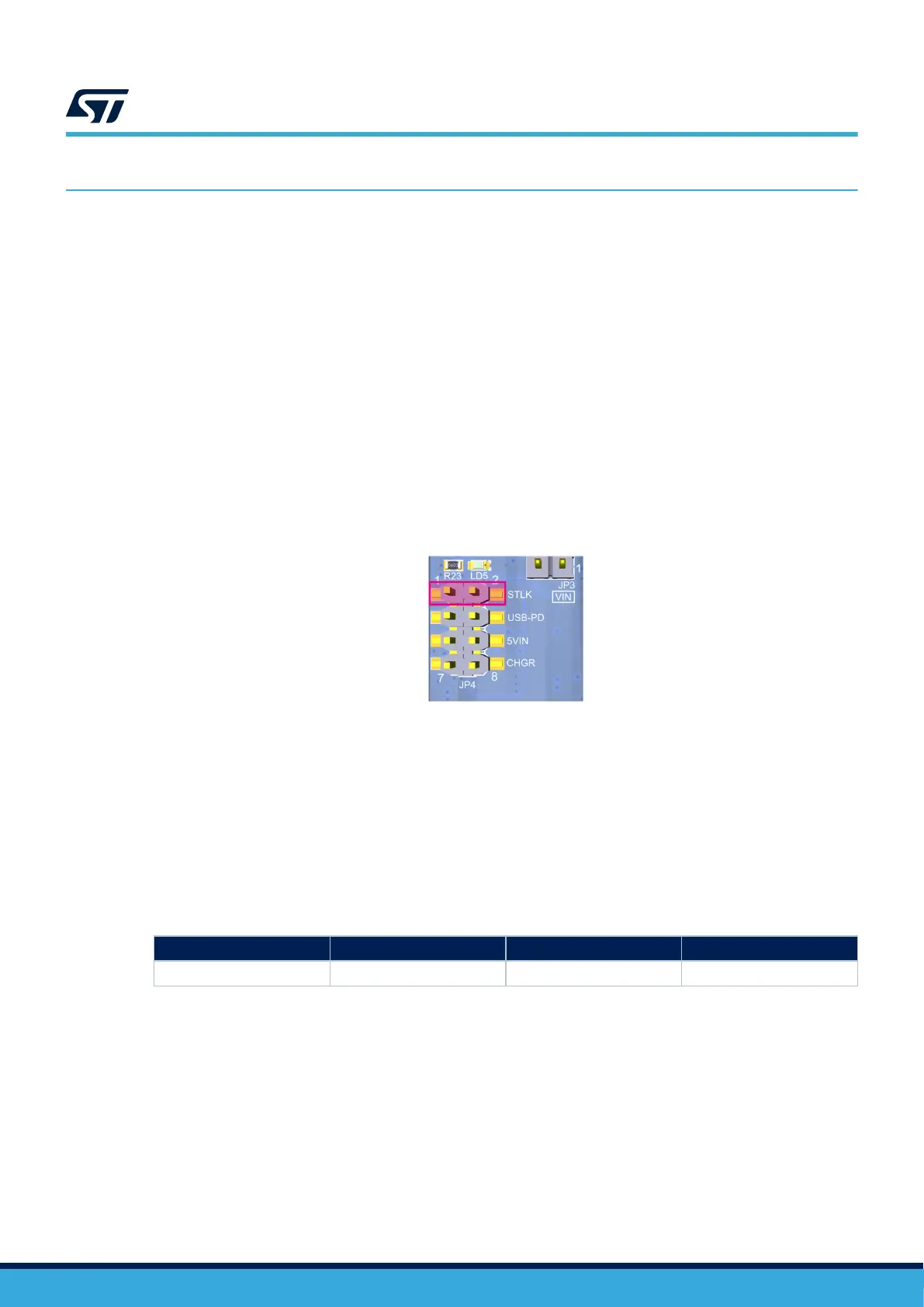
connector of the STM32H573I-DK via a USB cable. In this case, JP4 must be fitted on pin [1-2] to
select the STLK power source. This is the default setting.
Figure 8. JP4 set on the STLK pin
If the USB enumeration succeeds, the STLK power is enabled, by asserting the T_PWR_EN signal (from
STLINK-V3EC). This pin is connected to an over voltage protection (U34) with management of the max current
delivery.
• If the host can provide the required power, the U34 power switch is enabled, the green power LED (LD5) is
turned ON, and the
STM32H573I-DK board and its shield can consume up to 3 A max.
• If the host is not able to provide the requested current, the enumeration fails. The U34 power switch
remains OFF and the MCU part including the extension board is not powered. As a consequence, the
green power LED (LD5) remains OFF. In this case, it is recommended to use another external power
supply.
Table 6. External power source: 5V_STLK (5 V)
Input power name
Connector pins Voltage range Max. current
5V_STLK CN10 5 V 3 A
9.2 Supplying the board by VIN (7-12 V, 800 mA max.)
The STM32H573I-DK can be supplied also through the pin 1 of the CN14 ARDUINO
®
Uno V3 connector (marked
‘VIN’ on the board).
In this case, the 5 V power source selector (JP4) must be fitted between pin 5 and pin 6 to select the VIN power
source.
UM3143
Power supply
UM3143 - Rev 1
page 15/53

 Loading...


