Main features of the MB1400 Wi‑Fi
®
module:
• Support for 802.11 b/g/n
• Integration of ARM-CM4F, WLAN MAC / Baseband / RF
• 256‑Kbyte RAM / 2‑Mbyte flash memory
• Maximum transmission rate up to 72.2 Mb/s with 20 MHz of bandwidth
• Support for WPA / WPA2 PSK / TKIP
• Support for WPA / WPA2 Enterprise
• One SPI interface, one SWD, GPIOs
• Lead-free design, compliant with RoHS requirements
• EMI / EMC metal shield for best RF performance in noisy environments and to accommodate for lower RF
emissions/signature for easier FCC compliance
• FCC / ISED / CE compliance certification
Table 14. Wi‑Fi
®
module I/O configuration
STM32H573IIK3Q I/O Chipset pin
PH8 (STMO#8-MOSIs) CHIP_EN
PF8 (SPI5_MISO) MISO
PF9 (SPI5_MOSI) MOSI
PF7 (SPI5_SCK) CK
PF6 (SPI5_NSS) CS
Note:
The MB1400 Wi
‑
Fi
®
module operates at 3.3 V only.
14.9
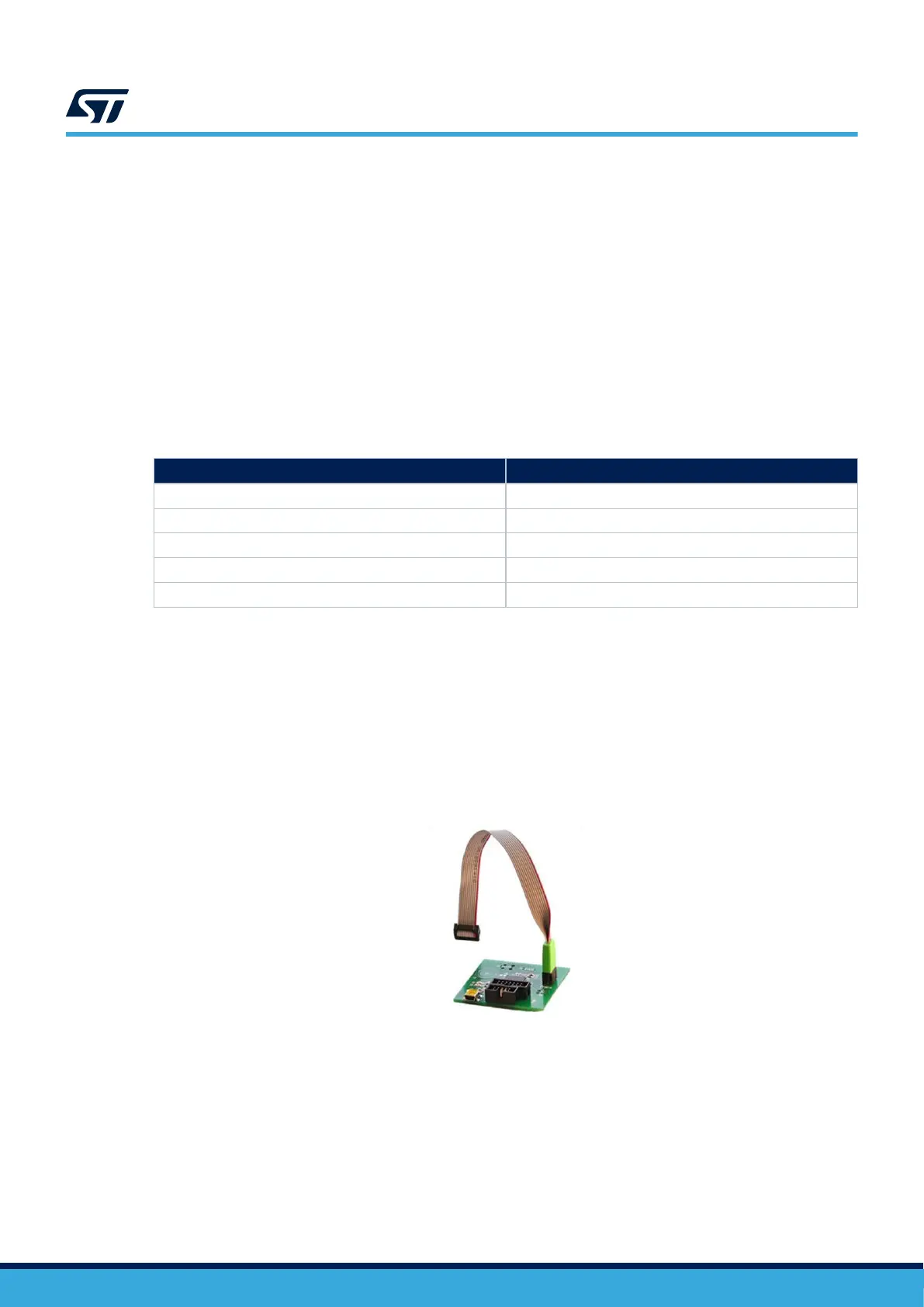
TAG
The STM32H573I-DK board includes one Tag‑Connect
™
footprint, to connect debuggers/programmers in a
simple way with a 10-conductor cable and without any extra accessory or equipment.
The 10-conductor cable can be plugged directly into the TAG connector footprint on the STM32H573I-DK
Discovery kit.
Figure 13. 10-connector cable
Note: The TAG supports 1.8 V or 3.3 V for target reference voltage.
14.10
JTAG/SWD/TRACE
The STM32H573I-DK Discovery kit offers different ways to connect an external debugging/programming probe.
Depending on the debugger tool and used cable, the STM32H573I-DK offers 10-pin or 20-pin target board
connector solutions.
UM3143
TAG
UM3143 - Rev 1
page 26/53

 Loading...


