The related pinout for the STMod+ connector is listed in Table 20.
Table 20. STMod+ connector CN3 pinout
Pin number Description Pin number Description
1
SPI5_NSS / USART7_CTS
(PF6/PF9)
11 INT (PH9)
2
SPI5_MOSI / USART7_TX
(PF9/PF7)
12 RESET (PH6)
3
SPI5_MISO / USART7_RX
(PF8/PF6)
13 ADC (PF11)
4
SPI5_SCK / USART7_RTS
(PF7/PF8)
14 PWM (PH12)
5 GND 15 +5V
6 +5V 16 GND
7 I2C1_SCL (PB6) 17 IO (PF3)
8 SPI5_MOSIs (PH8) 18 IO (PB12)
9 SPI5_MISOs (PH7) 19 IO (PH4)
10 I2C1_SDA (PB7) 20 IO (PH5)
Limitation: on the STM32H573I-DK board, SPI5 and UART7 signals are used to control a device connected to
STMod+ or to Pmod
™
. Therefore, when using the STMod+ connector, the user must make sure that nothing is
plugged into the Pmod
™
connector.
15.4
Pmod
™
connector (CN6)
The standard 12-pin Pmod
™
connector is available on the STM32H573I-DK Discovery kit to support low
frequency, low
I/O pin count peripheral modules.
The Pmod
™
interface that has been implemented on STM32H573I-DK Discovery kit is compatible with the
Pmod
™
type 2A and 4A I/O signal assignment convention.
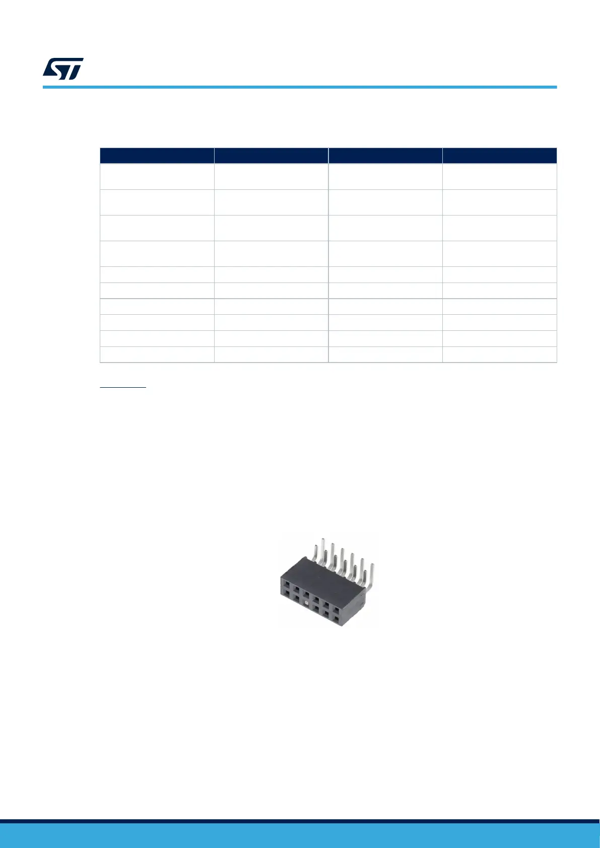
Figure 17. Pmod
™
connector CN6
The related pinout for the Pmod
™
connector is listed in Table 21.
UM3143
Pmod™ connector (CN6)
UM3143 - Rev 1
page 31/53

 Loading...


