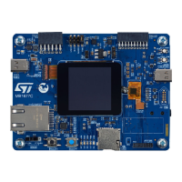
Figure 15. microSD
™
connector CN5
The related pinout for the microSD
™
connector is listed in Table 18.
Table 18. microSD
™
connector CN5 pinout
Pin number Description MCU port Pin number Description MCU
1 SDIO1_D2 PC10 6 GND -
2 SDIO1_D3 PC11 7 SDIO1_D0 PC8
3 SDIO1_CMD PD2 8 SDIO1_D1 PC9
4 VDD (3V3) - 9 µSD_Detect PH14
5 SDIO1_CK PC12 11-12-13-14 GND (casing) -
15.3 STMod+ connector (CN3)
A standard 20-pin STMod+ connector is available on the STM32H573I-DK board. The STMod+ connector
increases compatibility with external boards and modules from the ecosystem of microcontrollers. The STMod+
connector extends UART, SPI, I/Os signals for different peripheral expansion like Wi‑Fi
®
modules, cellular
modems, and such.
Solder bridges are here to configure the UART7 or SPI5 serial interface of the STM32H573IIK3Q MCU depending
on the external board to be controlled.
Table 19. STMod+ solder bridge configuration
Solder bridge
Settings Description
SB2, SB5, SB6, SB8
SB3, SB4, SB7, SB9
ON
OFF
UART7 connected to STMod+
SPI5 disconnected from STMod+
SB2, SB5, SB6, SB8
SB3, SB4, SB7, SB9
OFF
ON
Default configuration
UART7 disconnected from STMod+
SPI5 connected to STMod+
By default, the SPI5 bus is connected to control the MB1400 Wi‑Fi
®
module.
An MB1280 fan-out daughterboard is also provided with the STM32H573I-DK Discovery kit. For more information
on the MB1280 fan-out daughterboard, refer to the STMod+ fan-out daughterboard's user manual (UM2695) and
to the relevant datasheets of the associated modules.
For details about the STMod+ interface, refer to the STMod+ interface specification (TN1238).
Figure 16. STMod+ connector CN3
UM3143
STMod+ connector (CN3)
UM3143 - Rev 1
page 30/53

 Loading...