15 Board connectors
15.1
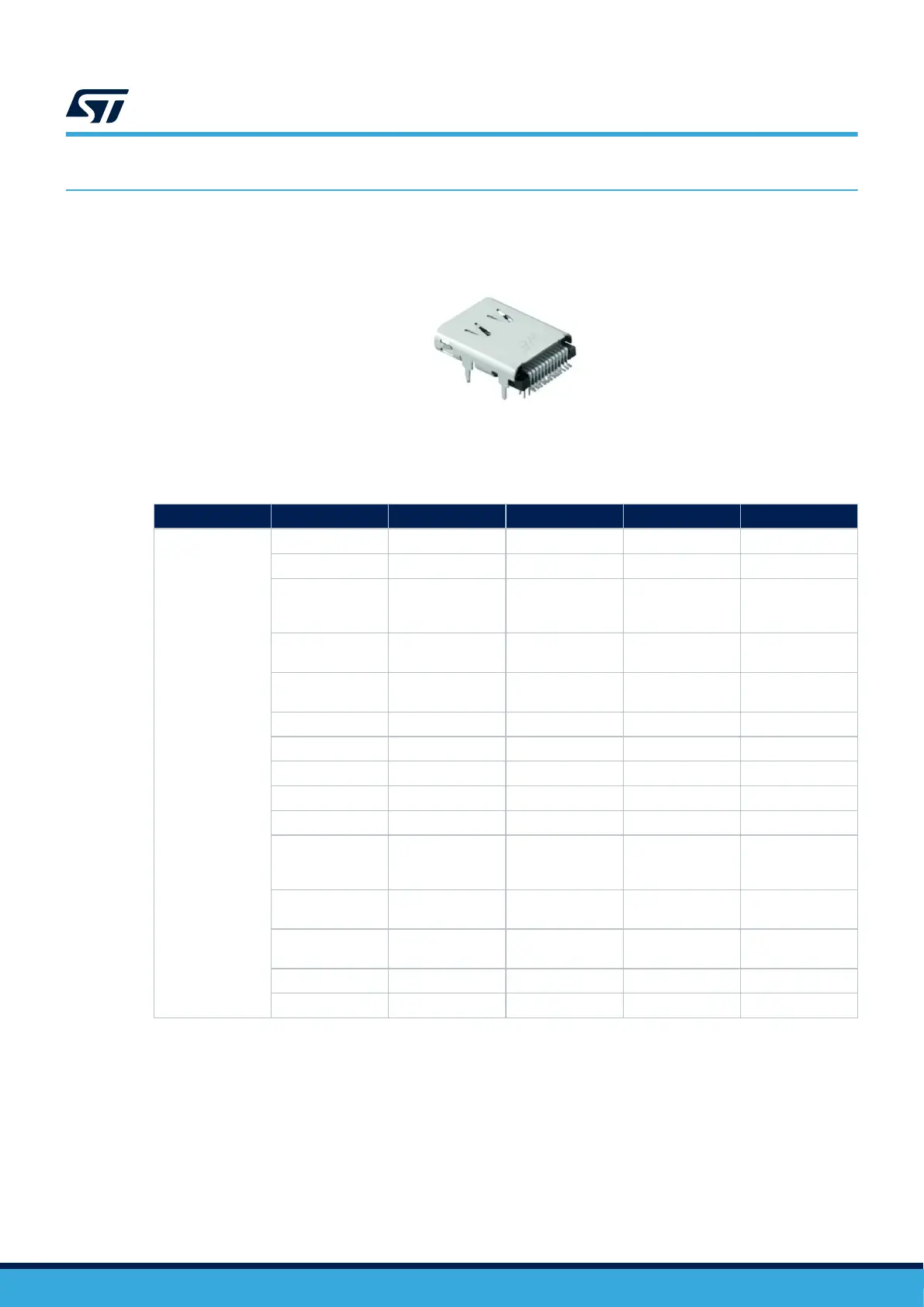
USB Type-C
®
connector (CN17)
Figure 14. USB Type-C
®
connector CN17
The related pinout for the user USB Type-C
®
connector is listed in Table 17.
Table 17. USB Type-C
®
connector CN17 pinout
Connector Pin number Pin name Signal name STM32H5 pin Function
CN17
A1 GND GND - Ground
A4 VBUS VBUSc - Power
A5 CC1 - PB13
USB-PD controller
side for the CC1
pin
A6 USB_P - PA12
USB differential
pair P
A7 USB_N - PA11
USB differential
pair M
A8 SBU1 - - -
A9 VBUS VBUSc Power
A12 GND GND - Ground
B1 GND GND - Ground
B4 VBUS VBUSc - Power
B5 CC2 - PB14
USB-PD controller
side for the CC2
pin
B6 USB_P - PA12
USB differential
pair P
B7 USB_N - PA11
USB differential
pair M
B9 VBUS VBUSc - Power
B12 GND GND - Ground
15.2
microSD
™
connector (CN5)
microSD
™
cards with 4 Gbytes or more capacity can be inserted in the connector CN5. Four data bits of the
SDIO1 interface, CLK, and CMD signals of the STM32H573IIK3Q are used to communicate with the microSD
™
card at 3.3 V only. The µSD_Detect signal detects the card insertion: when a microSD
™
card is inserted, the
µSD_Detect level is 0, otherwise it is 1.
UM3143
Board connectors
UM3143 - Rev 1
page 29/53

 Loading...


