Connector Pin number Description Pin number Description
CN8
4 TD- 11 Green LED (K)
5 TCT 12 Green LED (A)
6 RCT 13 SHIELD_1 (GND)
7 RD+ 14 SHIELD_2 (GND)
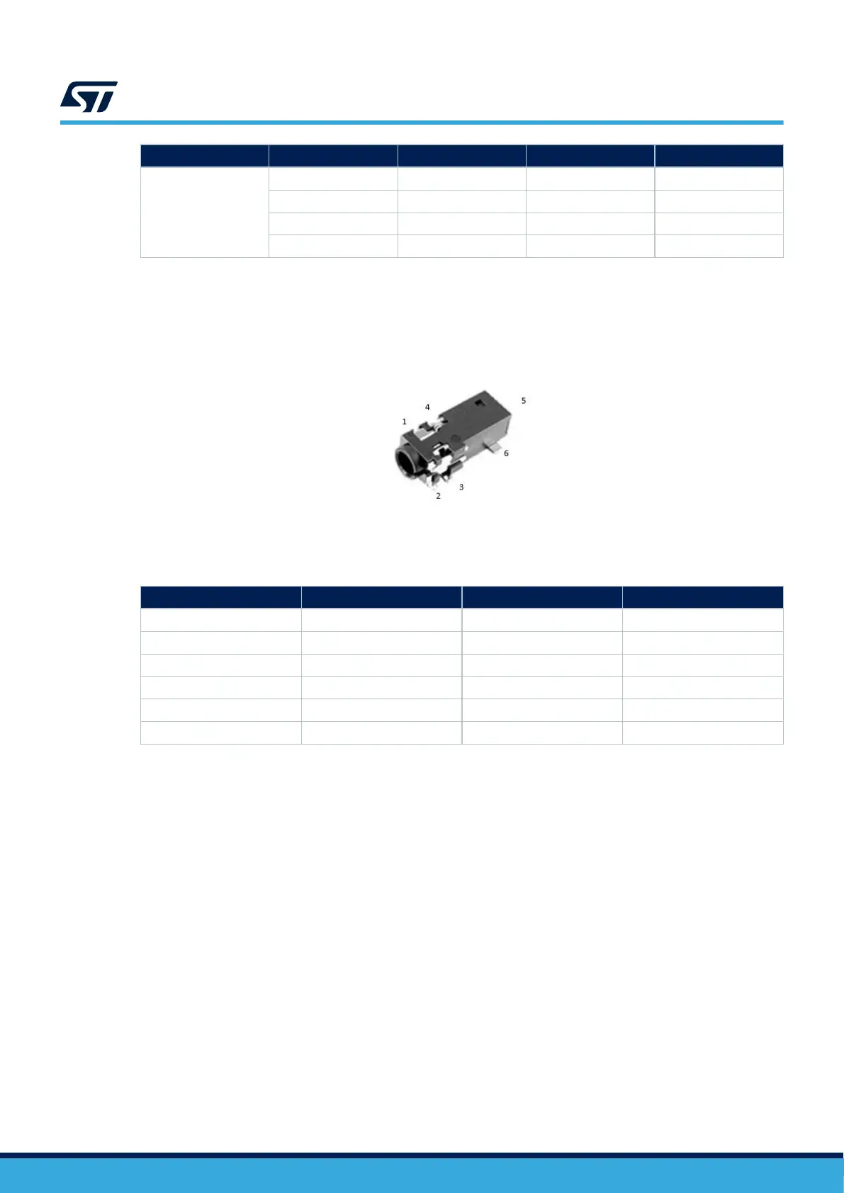
15.12 Audio jack connector (CN9)
A 3.5 mm standard stereo audio green jack output called CN9 is available on the STM32H573I-DK board for
headphones.
Figure 25. Audio jack connector CN9
The related pinout for the audio jack connector is listed in Table 30.
Table 30. Audio jack connector pinout
Pin number
Signal name Audio codec pin Function
1 Not connected Not available Not available
2 MIC_IN MICIN1/AIN3A Microphone input
3 GND - Ground
4 OUT_Right AOUTB HP right
5 Not connected Not available Not available
6 OUT_Left OUTA HP left
15.13
ARDUINO
®
Uno V3 connectors (CN13, CN14, CN15, CN16)
The ARDUINO
®
Uno V3 connectors CN13, CN14, CN15, and CN16 are female connectors. They are compatible
with the ARDUINO
®
Uno V3 standard. Most shields designed for ARDUINO
®
Uno V3 fit to the STM32H573I-DK
board.
Caution:
The STM32 microcontroller I/Os are 3.3 V compatible instead of 5 V for ARDUINO
®
Uno.
Table 31 shows the references of the ARDUINO
®
Uno V3 connectors.
Before using any ARDUINO
®
Uno V3 shield, it is important to refer to Section 9.1 Supplying the board by the
STLINK-V3EC USB Type-C
®
connector (default setting) for a correct configuration of JP4.
UM3143
Audio jack connector (CN9)
UM3143 - Rev 1
page 37/53

 Loading...


