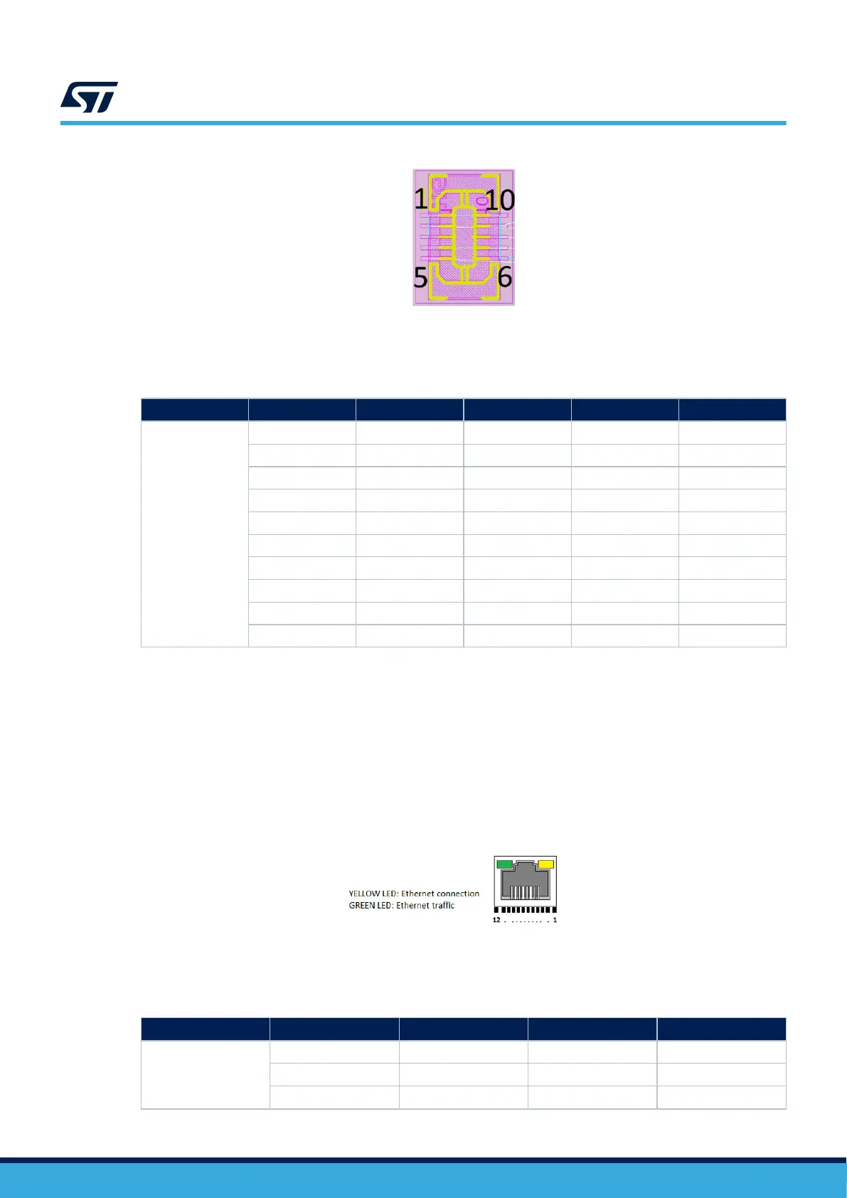
Figure 23. Touch panel connector CN4
The related pinout for the touch panel connector is listed in Table 28.
Table 28. Touch panel connector pinout
Connector Pin number Pin name Signal name STM32 pin Function
CN4
1 GND - - Ground
2 INT LCD_CTP_INT PG7 Interrupt
3 GND - - Ground
4 SDA I2C4_SDA PB9 I2CFMP1_SDA
5 SCL I2C4_SCL PB8 I2CFMP1_SCL
6 GND - - Ground
7 RESET LCD_CTP_RST PG3 Reset
8 GND - - Ground
9 VDD 3V3 - Power
10 GND - - Ground
15.11 Ethernet RJ45 connector (CN8)
The STM32H573I-DK board supports 10 Mbit/s / 100 Mbit/s Ethernet communication with its PHY and the CN8
integrated Ethernet RJ45 connector. The Ethernet PHY is connected to the MCU via the RMII interface.
The 25 MHz clock for the PHY is sourced from the on-board 25 MHz oscillator X3.
The 50 MHz clock for the MCU (derived from the 25 MHz crystal oscillator) is provided by the RMII_REF_CLK of
the PHY.
The yellow LED and the green LED are located inside the Ethernet RJ45 connector.
Figure 24. Ethernet RJ45 connector CN8
The related pinout for the Ethernet RJ45 connector is listed in Table 29.
Table 29. Ethernet RJ45 connector pinout
Connector
Pin number Description Pin number Description
CN8
1 Yellow LED (A) 8 RD-
2 Yellow LED (K) 9 NC
3 TD+ 10 CHS_GND(GND)
UM3143
Ethernet RJ45 connector (CN8)
UM3143 - Rev 1
page 36/53

 Loading...


