4-2
10083002 Operator Manual Post Installation Verification
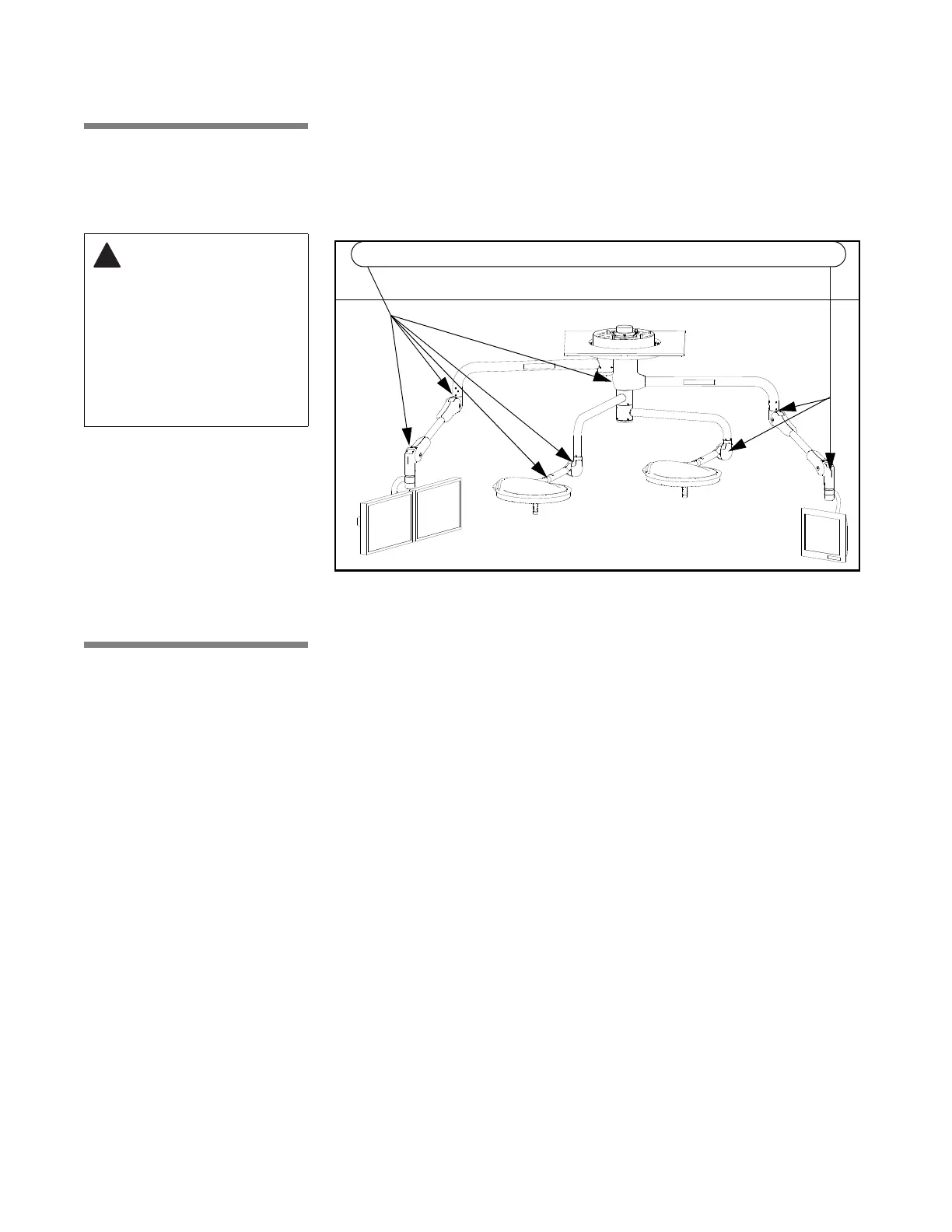
4.2 Check
Suspension
Movement
Check all suspension joints for compromised integrity, such as loose
fasteners or components. Refer to Figure 4-2 for typical points on the
suspension.
Verify that suspension system moves through all articulations smoothly without
binding. Lightheads and monitors should move smoothly and easily. When
positioned, the lighthead and monitor support arms should not drift. If binding
or drifting is present in suspension movements, call your STERIS service
representative to make adjustments.
4.3 Monitor Arms Refer to Figure 4-3. Flat panel monitor support arms are capable of the
following articulations: (1) rotate 240° at the secondary spindle; (2) rotate 320°
at the central spindle; (3) rotate 310° at the horizontal extension arm; (4) rotate
320° at the spring arm/yoke transition; (5) move up or down by pivoting at
spring arm knuckle up to 40° up, and 40° down. Flat panel yoke also allows
(6) tilt15° backward (up) and 90° forward (down).
• For additional information, refer to separate operating instructions
supplied with monitor(s). (Monitor instructions not by STERIS.)
• Power supply and input signals to monitors can be routed through the
suspension wiring from an external video source (external video sources
not provided by STERIS).
• Range of upward motion for spring arm can be adjusted to 20°, 30° or 40°
above horizontal to expand storage/parking options when monitors are not
in use.
If weight or range of motion for flat panel monitor mount system is changed in
any way, refer to I
NSTALLATION INSTRUCTIONS, 10043126 for procedures to help
ensure proper balancing and motion.
WARNING – PINCHING
HAZARD: Pinch points
are created during
extreme articulation of
the suspension
system. Do not place
hands on or near the
suspension knuckle
during lighthead
articulations.
Figure 4-2. Check Suspension
Check these, and all similar areas for ease of movement, as well as suspension integrity