43TS 410, TS 420
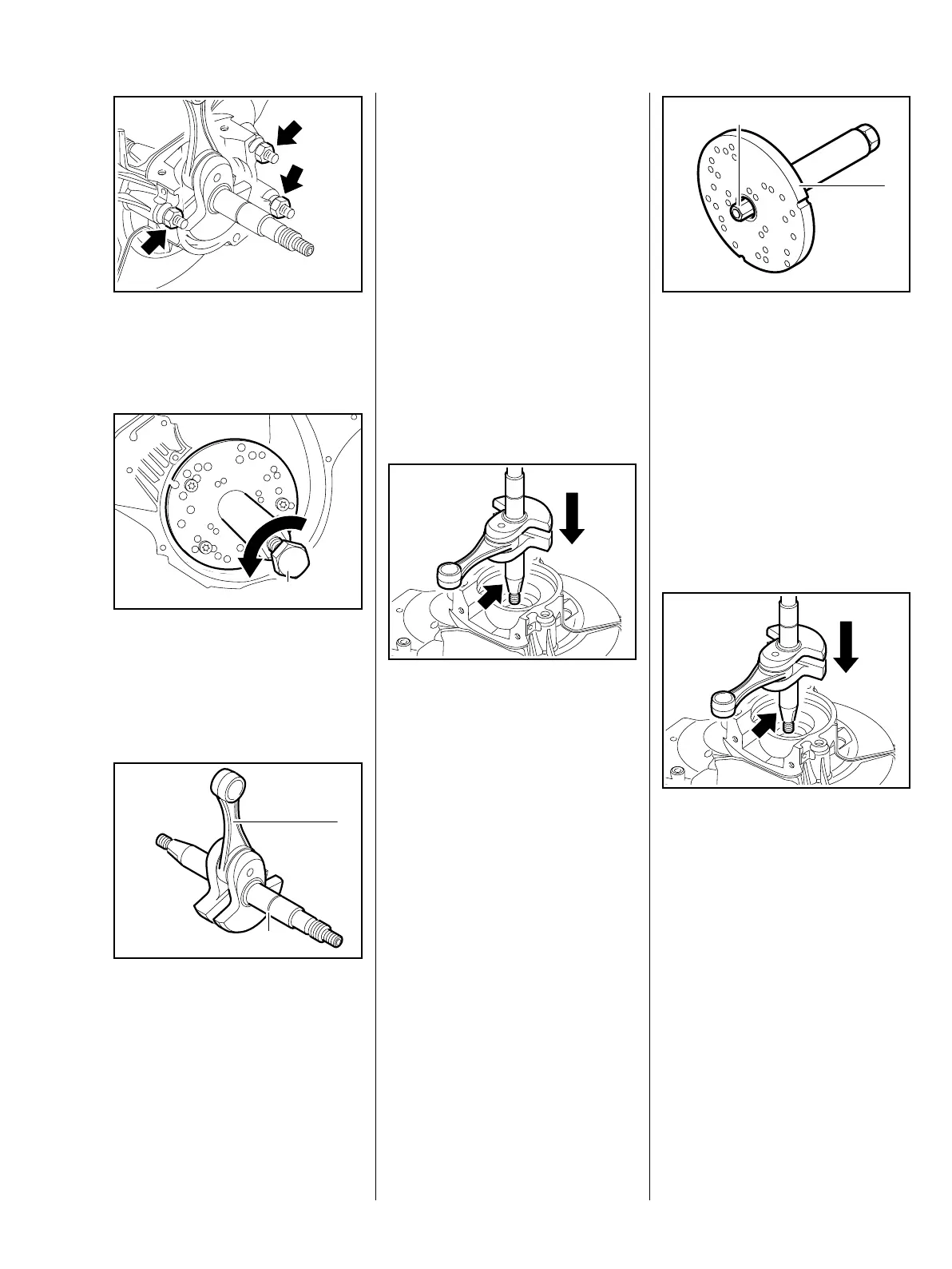
: Fit washers and nuts (arrows).
– Screw the nuts tight.
: Turn the spindle (1)
counterclockwise until the
crankshaft has been forced out of
the ignition-side half of the
crankcase.
: The crankshaft (1), connecting
rod (2) and the needle bearing
between them make up a
complete unit and must therefore
always be replaced as a unit.
– Check the two halves of the
crankcase and the grooved ball
bearing, replace if necessary,
b 7.6.2.
370RA142 TG
21
21
21
21
370RA143 TG
1
370RA144 TG
2
1
Before installing the crankshaft,
it must be cleaned with standard
solvent-based degreasant not
containing any chlorinated or
halogenated hydrocarbons.
Installing the ignition-side half of
the crankcase
Avoid damage to the crankshaft
stub.
Examine and clean the mating
surfaces of the ignition-side half of
the crankcase (including the
cylinder sealing surface). The
mating surfaces must not be
damaged in any way whatsoever.
– Line the crankshaft up with the
conical stub (arrow) pointing
towards the grooved ball bearing
on the ignition side.
Wear protective gloves – risk of
burns.
– Heat the inner race of the ball
bearing to approx. 150 °C
(300 °F).
Push the crankshaft home until the
crankshaft stub makes contact.
The crankshaft must be fitted
rapidly, as the heat is transmitted to
the crankshaft stub and the inner
bearing race contracts.
370RA145 TG
If the inner race cannot be heated,
the crankshaft can be drawn into the
crankcase with the installing tool
5910 893 2102.
: Fit the screw sleeve (1)
5910 893 2421 as far as possible
over the fully retracted spindle of
the installing tool (2)
5910 893 2102.
Coat the conical crankshaft stub
with oil.
.
: Align the crankshaft with the
conical stub (arrow) facing the
ignition-side ball bearing and
push it home.
370RA146 TG
1
2
370RA145 TG

 Loading...