TS 44042
N Undo screw (4).
N Remove air baffle (5) and support foot (3).
N Pull stop buffer (6) out of air baffle (5).
N Pull wiring harness (7) out of the air baffle (5).
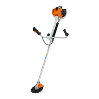
17.3 Installing control panel – electronic module wiring
harness
N Push wiring harness (7) and protective tube as far as
they will go into support (10).
N Slide protective tube (11) toward the grommet.
N Press the wires of the wiring harness (7) into the
guides (arrows) with the aid of the wiring tool. The
black wire must run underneath the blue wire.
N Push stop buffer (6) into air baffle (5).
N Protective tube (11) must be located between
grommet and air baffle (5).
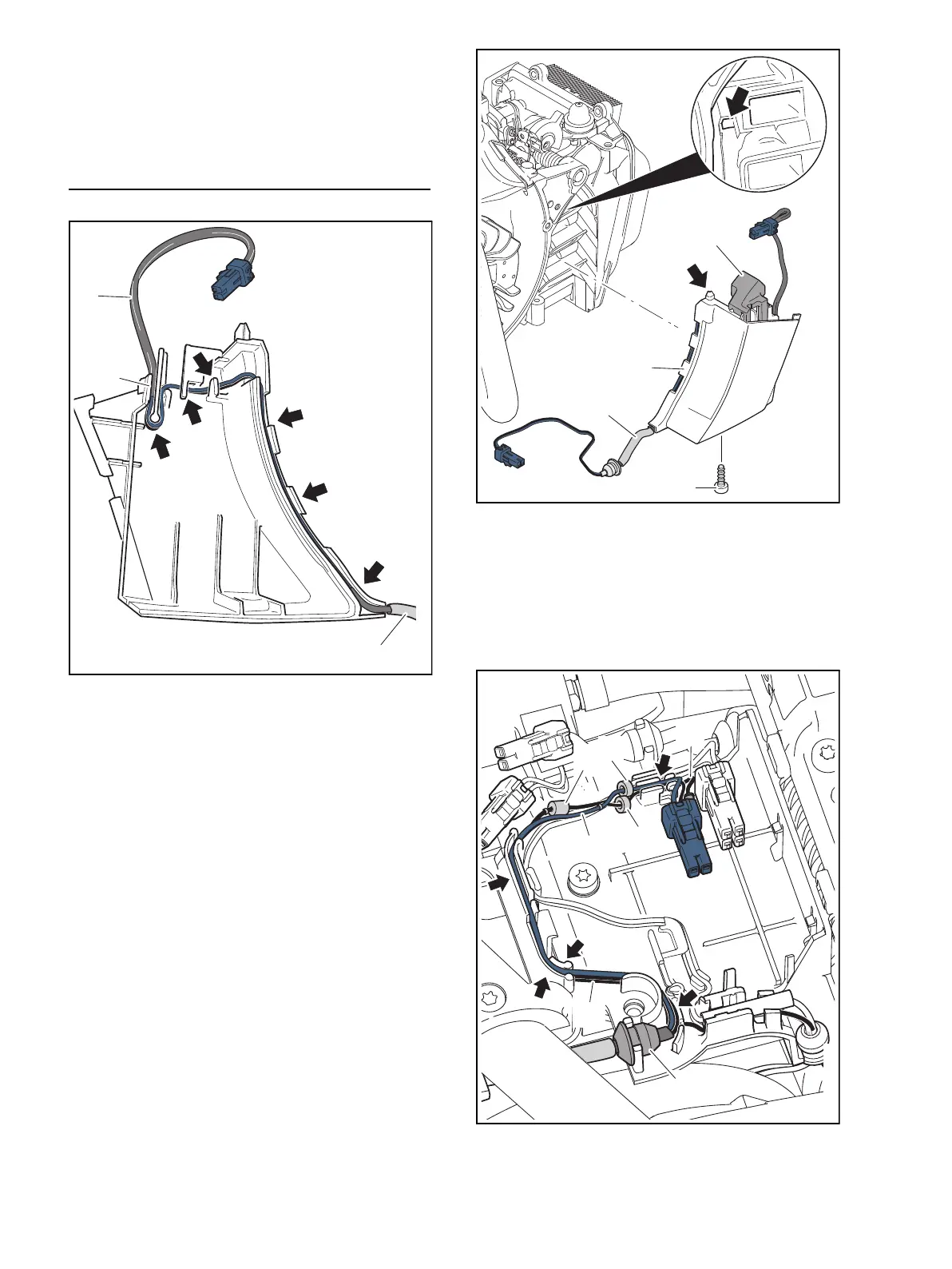
N Insert air baffle (5) along with support foot (3) and
wiring harness (7). The lug (arrow) engages with the
recess (arrow).
N Insert screw (4) and tighten.
N Pass wiring harness (7) between handlebar and
engine housing.
N Press grommet (9) into the guide rib.
5
0000-GXX-0901-A2
6
P6x19 (6 Nm / 53 lbf. in.)
4
11
0000-GXX-0463-A1
9
13
13
14
7
12
12

 Loading...