STOBER 9 | Monitoring and diagnostics
02/2020 | ID 442516.07
45
9 Monitoring and diagnostics
For monitoring purposes and in the event of a fault, the various monitoring and diagnostic options described below are
available.
9.1 Connection monitoring
In order to be able to detect a communication failure, activate the watchdog function. This means that you monitor the
arrival of cyclical process data by defining a PDO timeout in A258 EtherCAT PDO-Timeout (see the chapter Parameterizing
general EtherCAT settings [}25]).
In the Operational operating state, an activated watchdog triggers fault 52: Communication with cause 6: EtherCAT PDO off
if a new PDO is not received within the specified timeout.
Monitoring is not triggered if the EtherCAT master regularly ends communication by leaving the operational state.
9.2 LED display
STOBER drive controllers feature diagnostic LEDs that visualize the state of fieldbus communication and the states of the
physical connection.
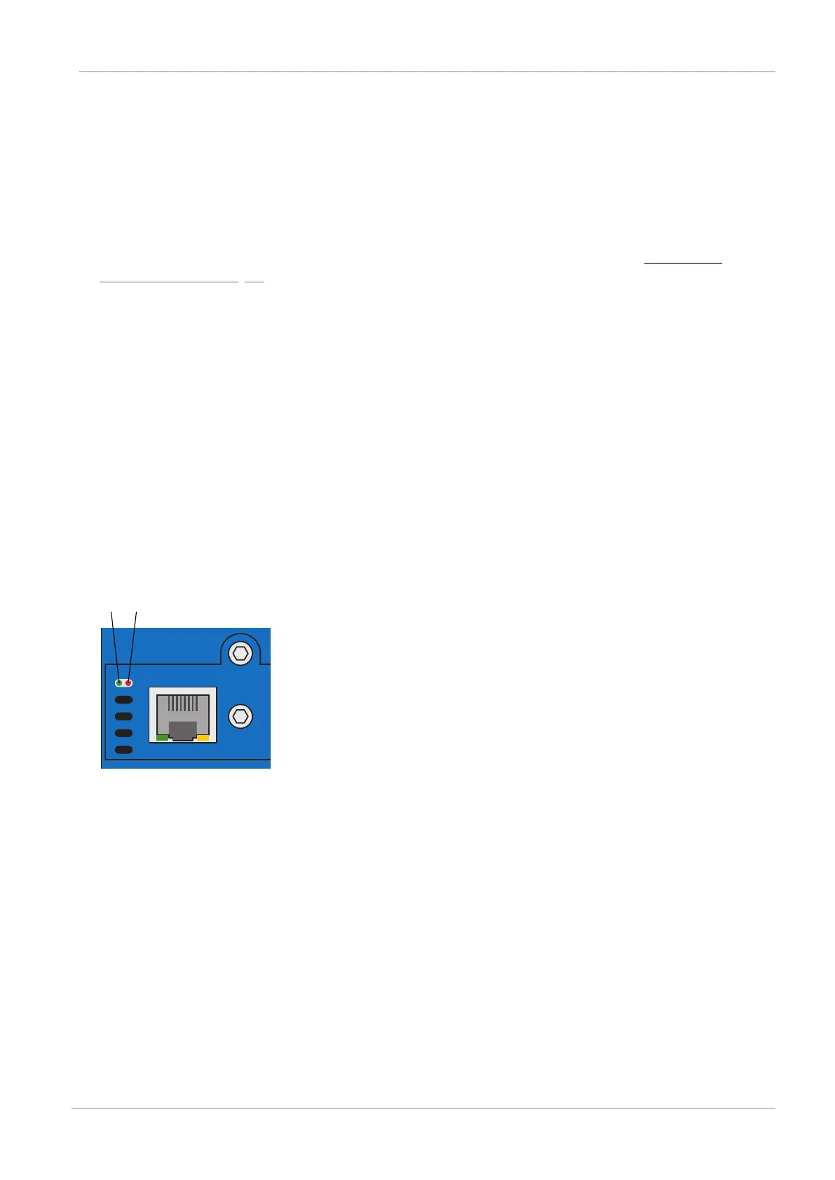
9.2.1 EtherCAT state
There are 2 LEDs on the top of the drive controller that provide information about the connection between the EtherCAT
master and slave and about the state of the data exchange. This information can also be read out in parameter A255
EtherCAT Device State.
Fig.6: LEDs for the EtherCAT state
1 Green: Run
2 Red: Error