PPrroocceedduurree::
1. Pull the trolley assembly out of the patient compartment until it locks into the loading position.
NNoottee -- This makes working on the product easier, but is not required.
2. Remove the hydraulics assembly. See
Hydraulics assembly removal and replacement
(page 41).
3. Using two 9/16" combination wrenches, loosen (do not remove) the hose end connectors (A) from the manifold to
remove both hoses (Figure 41).
NNoottee -- Hydraulic fluid will leak from the cylinder and hoses. Lay down towels to catch fluid.
FFiigguurree 4411 –– HHyyddrraauulliiccss aasssseemmbbllyy hhoossee eenndd ccoonnnneeccttoorrss
4. Reverse steps to reinstall.
5. Verify proper operation before you return the product to service.
MMoottoorr ccaabbllee rreemmoovvaall aanndd rreeppllaacceemmeenntt
TToooollss rreeqquuiirreedd::
• 7/16'' combination wrench
PPrroocceedduurree::
1. Pull the trolley assembly out of the patient compartment until it locks into the loading position.
NNoottee -- This makes working on the product easier, but is not required.
2. Remove the trolley covers. See
Cover removal and replacement
(page 35).
3. Remove the hydraulics assembly. See
Hydraulics assembly removal and replacement
(page 41).
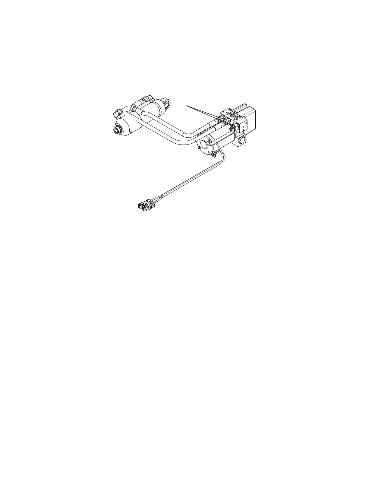
4. Using a 7/16" combination wrench, remove the two nuts (A) and star washers (B) that secure the motor cable (C) to the
motor assembly (Figure 42).
NNoottee -- Pay attention to the cable routing and terminal orientation for reinstallation.
EN 56 6390-309-002 Rev AB.0
 Loading...