FFiigguurree 1144 –– TTrroolllleeyy aasssseemmbbllyy
26.Position the trolley assembly (T) between the transfer assembly (U) and head end of the anchor assembly (V) on the
floor (
Figure 15).
27.Installer 1 (foot end): Slide the rollers of the trolley assembly into the side channel of the transfer assembly.
28.Installer 2 (head end): Lift the trolley assembly to align the second set of rollers and slide the rollers until the trolley is
near the middle of the transfer.
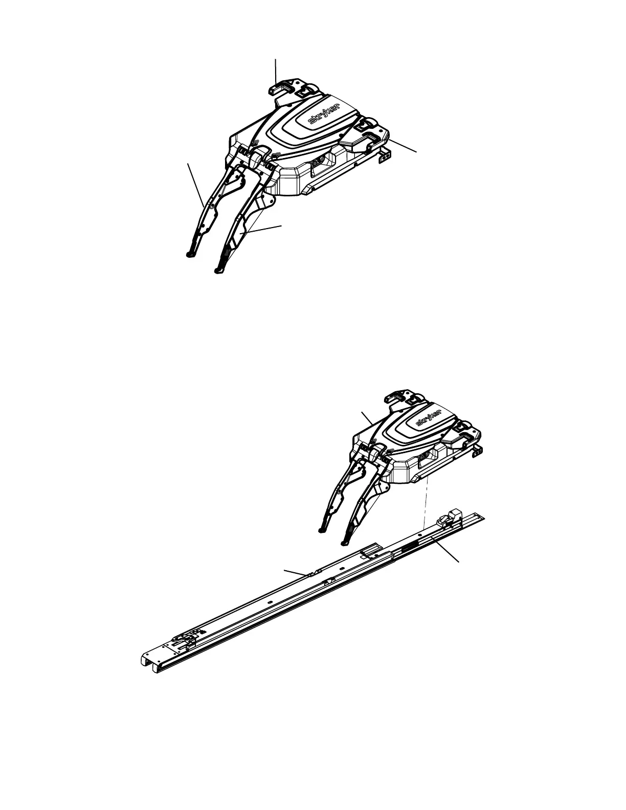
FFiigguurree 1155 –– PPoossiittiioonn tthhee ttrroolllleeyy aasssseemmbbllyy
29.Carefully push the transfer assembly forward toward the head end until it locks into position.
6390-709-001 Rev AB.1 21 EN
 Loading...