STULZ E
2
SERIES CONTROLLER FOR PERIMETER SYSTEMS OPERATION MANUAL
4
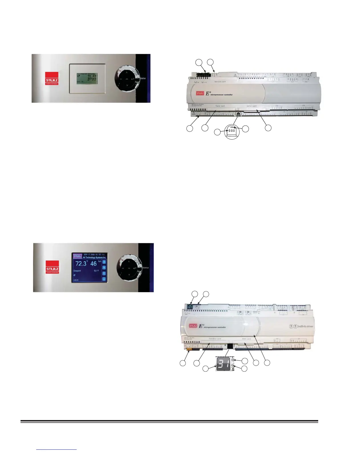
2.3.2 Large Bezel Terminal
The large bezel terminal is typically mounted on the door of
the A/C cabinet. It features the same backlit liquid-crystal
alphanumeric display screens that the graphicterminaluses.
A round membrane type keypad is provided to the right of the
display screen to navigate through the controller menus and
adjust operating parameters. The symbols on the round keypad
are operationally identical to the function keys on the graphic
terminal (see section 2.3.1.1).
When the A/C unit is on, a soft blue light illuminates the "Status"
region on the right side of the terminal indicating normal
operation. If the color of the "Status" region changes to red, it
indicates an alarm condition. As with the graphic terminal, an
alarm is acknowledged by pressing the alarm symbol on the
round keypad. After an alarm condition is corrected, the alarm
can be cleared by pressing the alarm symbol again. This resets
the A/C system and turns the color in the status region back
to blue.
2.3.3 Large Bezel Touch Screen Terminal
A large bezel terminal with touch screen is available with
certain A/C models. If the A/C unit is equipped with a touch
screen terminal, refer to the addendum OZU0074 (provided
under separate cover) for supplemental instructions.
2.4 Controller Models
The controller is a microprocessor with I/O modules mounted
inside the A/C system electric box (see Figure 2 and Figure 3).
The controller contains the software that manages the operating
parameters of the A/C system. Several I/O module types are
available depending upon the options that are needed with the
air conditioning system.
2.4.1 GEN1 Controller Layout
The GEN1 controller is shown in Figure 2.
1
2
4
3
6
5
7
The controller features called-out in Figure 2 are:
1. RJ11 telephone connector (J10) for display panel.
2. RS485 Connection for pLAN (J11).
3. Hatch for BMS or network interface port (see Figure 1).
4. Power on LED (Yellow).
5. Signal LEDs (Red, Yellow, Green). See Section 8.4.
6. Hatch for expansion I/O module(s).
7. Power connector (J1).
2.4.2 GEN2 Controller Layout
The GEN2 controller has additional input/output terminals for
expanded capability. It may be expanded with a built-in EVD
driver, utilized when electronic expansion valve(s) are provided.
The GEN2 controller is shown in Figure 3.
1
2
5
4
8
6
9
3
7
Figure 2. GEN1 Controller
Figure 3. GEN2 Controller