STULZ E
2
SERIES CONTROLLER FOR PERIMETER SYSTEMS OPERATION MANUAL
14
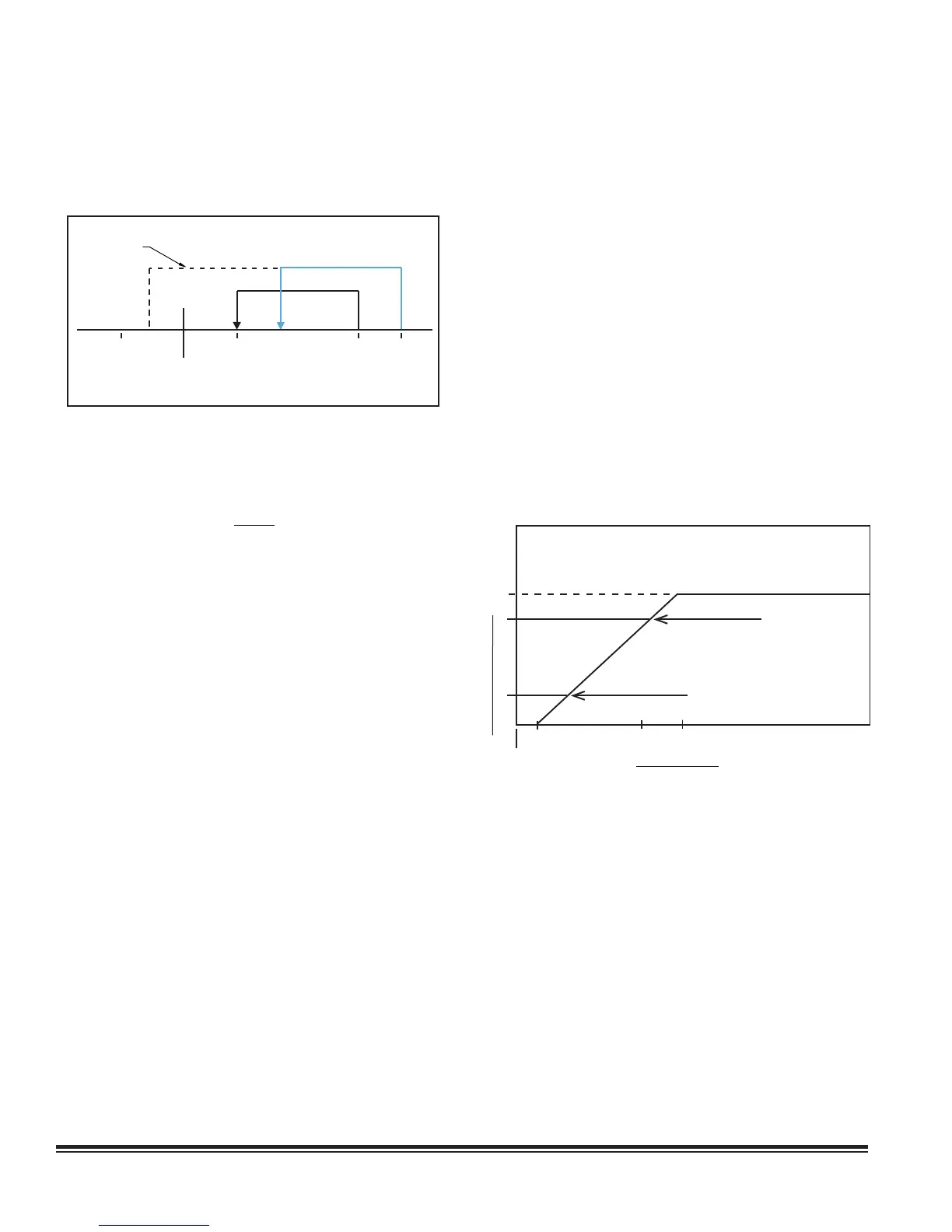
The compressor(s) are turned off in stages when the control
setpoint for each stage is achieved. To promote equal run
times, the controller is programmed in the Factory level menu
to rotate which compressor operates for the fi rst cooling stage
after each duty cycle.
Set
Point
Cut-in
1
Cut-in
2
Cut-out
1
Cut-out
2
Start
1
Start
2
Stop 1
Stop 2
Minimum
Run Time
Dehum
Min Temp
The cooling cut-in and cut-out setpoints should be set with a
minimum span of 2.0 °F.
NOTE
If the cooling cut-in/cut-out setpoints are set too
closely together when adjusting setpoints, the
compressor could run below the setpoint temperature
during periods of light heat loads because of the
minimum run time cycle.
4.5.1.2.1 Electronic Expansion Valve (EEV)
The controller may be programmed to manage the operation
of a EEV for each refrigeration circuit. The controller manages
the EEV based on input signals from suction pressure and
temperature sensors. The EEV maintains constant superheat at
the outlet of the evaporator by metering the fl ow of refrigerant
into the evaporator. By controlling superheat, the EEV keeps
nearly the entire evaporator surface active while preventing
liquid refrigerant from returning to the compressor. Adjustments
may be made by entering the Service>Sensors menu.
4.5.2 Energy Savings Confi gurations
There are several types of energy savings configurations
available: Economizer, Free-cooling (FC) and Alternate Water
Source (AWS). A W/G unit, where the condenser is cooled by a
liquid, can have an optional free cooling (FC) feature that takes
advantage of low temperatures of the W/G source. On AWS DX
(Alternate Water Source Direct Expansion) systems, there is a
separate W/G cooling coil that is used for cooling provided the
entering W/G temperature is low enough for it to be utilized.
4.5.2.1 Economizer
The economizer option enables the E
2
controller to minimize
or eliminate chilled water or compressor operation by utilizing
outside air when possible to satisfy temperature and humidity
demand and maintain the programmed setpoints. See Section
6.0 for an overview of economizer operation.
4.5.2.2 Alternate Water Source Cooling (AWS)
An AWS system (set at the Confi guration Level) utilizes an
independent chilled water source to provide coolant to an AWS
cooling coil which is located in the AC unit with the DX cooling
coil. When the Energy savings monitor option is set to “Yes”
in the Factory>Cool>Energy Savings menus, the entering
water temperature to the AWS coil is monitored and when that
temperature falls below the minimum value to use the AWS coil,
the AWS logic is enabled.
When the return temperature rises above the temperature
set point by the value set in Cut-out (0.3 °F by default), the
valve begins to open from the closed or 0% position. As the
temperature rises, the valve opens further in a manner that
makes it reach 100% open when the return temperature is at set
point plus the Band (20.0 °F by default) due to the proportional
component of the PID control of the CW valve. The Cut-out and
Band values are adjustable in the Service>Cool>CW,AWS,FC
menu.
Note that the actual voltage output to the valve for 0% and
100% are settable in the Factory>AnalogOut menu. The
defaults are 0.0 Volts for 0% and 10.0 volts for 100%.
0
Compressor on when valve
opens to this point
CW Valve Position
100%
Compressor off when valve
closes to this point
CW Valve Start
CW Valve
End
Setpoint
+CW cut-out
+Band
Temperature
The compressor assist works off of the valve position, thus it
is indirectly controlled by the return temperature, not directly.
When the valve opens due to the return temperature rising and
reaches the value set by CW Valve Start (100% by default) and
the time after reaching the CW Valve Start value has exceeded
the Start DX delay, the compressor is enabled. When the valve
closes due to the return temperature dropping and reaches the
value set by CW Valve End (10% by default), the compressor is
disabled. The CW Valve Start value does not have to be 100%;
it can be lowered to assist sooner in the CW valve stroke. If the
CW valve control has an integral component, it is best to leave
CW Valve Start value at 100% as the CW valve position will
increase over time to reach 100% if the return air temperature
remains constant above the Cut-Out value or continues to rise.
The CW Valve Start, Start DX delay and CW Valve End values
are adjustable in the Factory>Cool>Energy Savings menus.
There are three ways the AWS and DX circuits interact. These
Figure 6. Cooling On/Off Cycle
Figure 7. AWS/FC/DX Operation