STULZ E
2
SERIES CONTROLLER FOR PERIMETER SYSTEMS OPERATION MANUAL
3
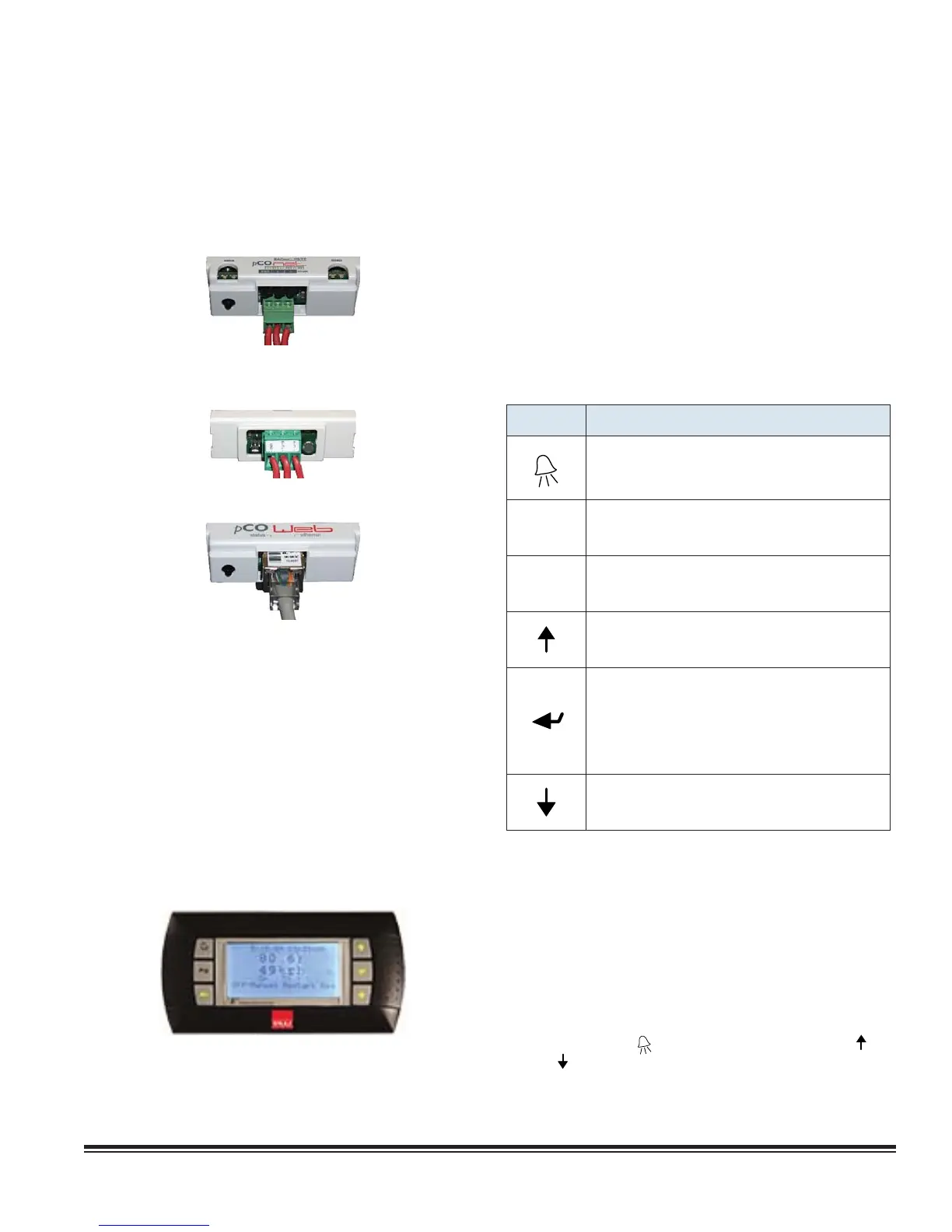
2.2.6 BMS Interface
The STULZ E
2
Series controller may incorporate a
communication interface port (Figure 1) that can be field
connected to a Building Management System via Modbus,
BACnet, SNMP or HTTP protocol as confi gured by the factory.
A controller interfaced to a network must be confi gured for BMS
communication.
BACnet IP, BACnet Ethernet,
HTTP, SNMP, & Modbus IP
BACnet MS/TP
Modbus RTU
2.3 User Interface Terminals
Several user interface terminals are available with STULZ E
2
Series controllers. The A/C unit may be equipped with a large
bezel terminal typically mounted on the door of the unit or a small
bezel terminal (termed "graphic terminal") which may be door
mounted or remotely mounted to a wall or control panel. See the
following sections for an overview of the user interface display
panels available.
2.3.1 Graphic Terminal
The STULZ graphic terminal features an easy to read, backlit
liquid-crystal alphanumeric display equipped with LED
illuminated function keys. The screens that appear on the display
present data that originates from the controller. The controller
is operated via 6-key menu-driven loop structure and offers
an alarm log plus four different interface menu levels to the
operator: Information, Control, Service, and Factory. These
menus permit the user to easily view, control and confi gure
operating parameters for the A/C unit (see Menu Selections,
Figure 4).
As an option, the graphic terminal may be shipped loose
for remote mounting. It may be located directly on a wall or
control panel using the mounting kit provided. Install the
terminal in a secure area where it cannot be tampered with. A
30 foot long RJ11 telephone type cable harness is provided
for interconnecting the display to the controller. Refer to the
electrical drawing supplied with the unit for details on the
interconnecting fi eld wiring.
2.3.1.1 Function Keys
KEY FUNCTION
Accesses the active alarm screen(s)
Silences audible alarms
Resets active alarms in the alarm menu
Prg
Accesses the main menu
Illuminates yellow when unit is on
Esc
Returns to the previous menu level
Cancels a changed entry
Steps back to the previous screen in display menu
Changes (increases) the value of a modifi able fi eld
Starts/Stops operation (if "Auto-On Powerup" isn't
enabled)
Moves the cursor into a modifi able fi eld
Accepts current value of a modifi able fi eld
Steps to the next screen in display menu
Changes (decreases) the value of a modifi able fi eld
2.3.1.2 Alarms
Alarm conditions activate a red LED indicator that backlights the
alarm function key. As an option, an alarm condition may also be
enunciated by an audible alarm signal. An alarm is acknowledged
by pressing the alarm key. This calls up alarm display screen(s)
that provide a text message detailing the alarm condition(s).
After an alarm condition is corrected, the alarm can be cleared
by pressing the alarm key.
2.3.1.3 Contrast Adjustment
Press and hold the ( ) and (Prg) keys; then use the Up ( ) and
Down ( ) keys to adjust the contrast.
Figure 1. BMS Interface Ports