STULZ E
2
SERIES CONTROLLER FOR PERIMETER SYSTEMS OPERATION MANUAL
21
Press ( ) or ( ) Key
1
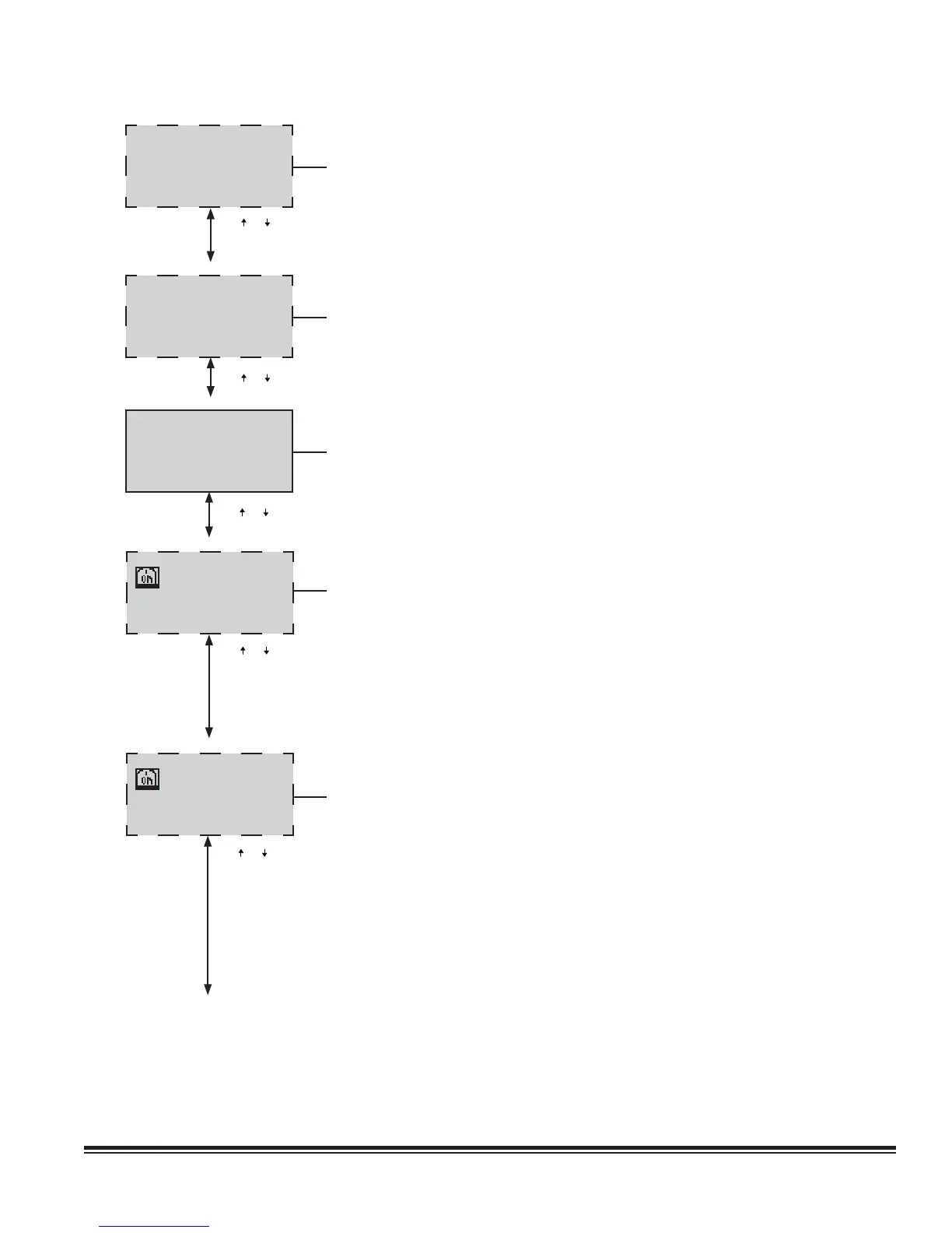
ALARM ON UNIT 9
SMOKE SHUTDOWN
AIR DX Heat Hum
Flow T/H Sensor
5.2.2 Shadow Unit Alarms
Shadow unit alarm messages appear in the controller display of the main unit when
an alarm occurs to a unit in the shadow group assigned to the main unit. The top
line of the fi rst menu screen is the display number assigned to the shadow group.
The next line is the unit number of the fi rst shadow unit in the shadow group. The
remaining messages shown are alarm conditions which appear only if the particular
alarm has occurred on the fi rst shadow unit.
ALARM ON UNIT 10
SMOKE SHUTDOWN
AIR DX Heat Hum
Flow T/H Sensor
Press ( ) or ( ) Key
The top line is the unit number of the second shadow unit in the shadow group. The
remaining messages shown are alarm conditions which appear only if the particular
alarm has occurred on the second shadow unit.
Press ( ) or ( ) Key
Return Sensor
00.0°F
00%rh
return dewpoint 00.0°F
5.2.3 Return Sensor
This screen displays Temperature and Relative Humidity as measured by the
return temperature and RH sensor inputs. The return dewpoint is calculated by
the controller based on the return sensor inputs and shown at the bottom of the
display screen.
Compressor 1 Status
LP:C
HP:C
Min On
Starts: 0 0hrs
Press ( ) or ( ) Key
* See Note
5.2.4 Compressor Status- (DX based systems)
This screen displays the On or Off status icon for the A/C system compressor(s) and
shows the status of the Low Pressure and High Pressure switches (Open or Closed).
The fi eld beneath the status icon indicates if the compressor is in the “minimum time
on” or “minimum time off” delay period. The fi eld at the bottom of the screen shows
the number of compressor starts since power was applied and the total compressor
run-time during the period since the last reset was performed in the Service>Run
Hours menu. If the system has more than one compressor, similar compressor status
display screens are provided for each compressor.
Compressor 1 Status
LP:C Suct P:000
HP:C Suct T:000
°F
Rst:Off 111 Disch: 295
High Press:0 HPC: 25%
Superheat:14
°F
Starts: 0 0hrs
Press ( ) or ( ) Key
5.2.4.1 Optional Compressor Status Fields
If the controller is confi gured for optional Suction Pressure Fan Speed Control (see
Section 4.6.4), it will be programmed to monitor an analog suction pressure sensor
and display the current value (Suct P). If optional Suction Temperature and Superheat
Temperature Sensors are provided for EEV valve control (see Section 4.5.1.2.1), the
controller will display the values (Suct T), (Superheat).
If the controller is confi gured for optional High Pressure With Auto Reset (see Section
5.4.1.1), it will be programmed to monitor an analog discharge pressure sensor. With
this option, a restart (Rst) value appears instead of Min Off if the compressor turns off
due to a high discharge pressure condition. The restart value is a countdown timer
showing the compressor minimum off delay time remaining before it is allowed to
restart again. The controller will also display the current discharge pressure value
(Disch). A value in the fi eld (High Press) indicates how many times the controller has
attempted to restart the compressor after a high pressure shutdown.