STULZ E
2
SERIES CONTROLLER FOR PERIMETER SYSTEMS OPERATION MANUAL
63
8.4 Control I/O Module Signal LED's
The GEN1 STULZ E
2
controller includes 3 signal LED's (red, yellow and green) that provide information on the operation of the
control module and status of the connection to the pLAN. These signal LED's are positioned adjacent to the yellow, "Power On" LED
(see Figure 2). The signal LED's may be used for diagnostic purposes if a problem arises with the controller.
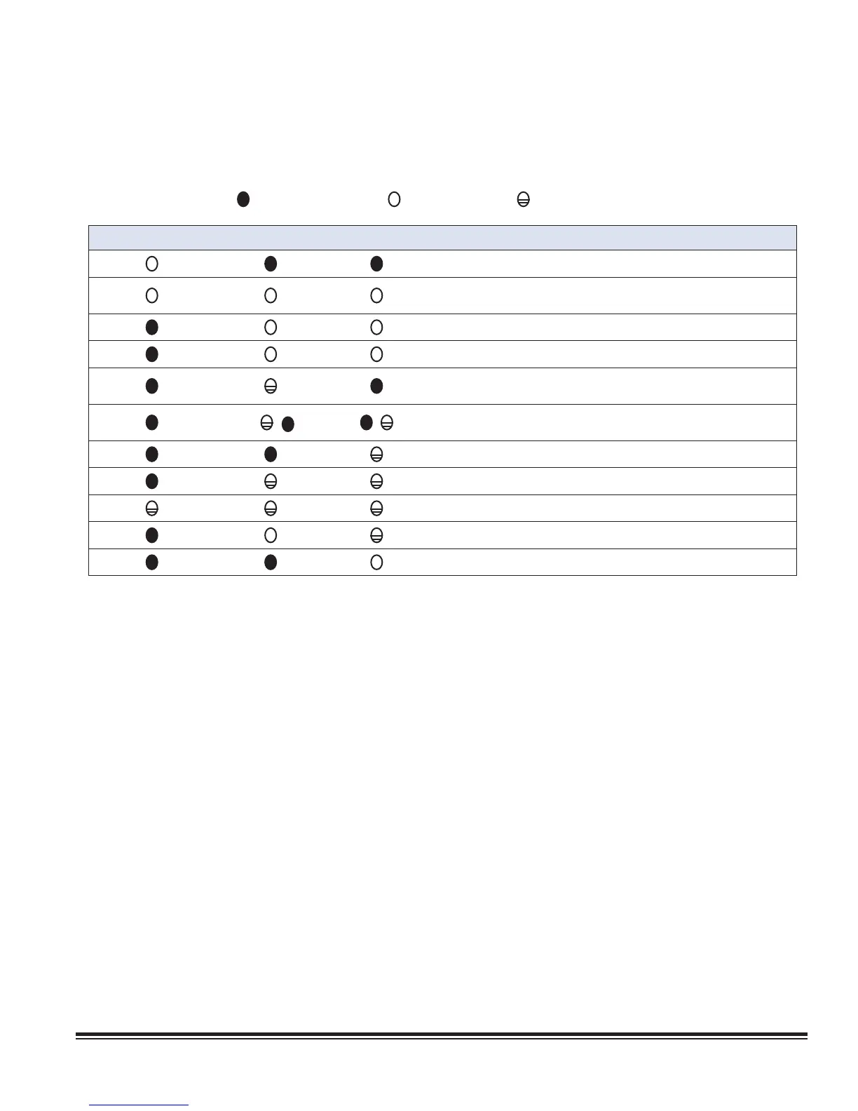
Key:
LED off LED on
LED fl ashing
RED LED YELLOW LED GREEN LED
Application with error or no pLAN table.
Application with error or no pLAN table. Controller connected to
ONLY one terminal.
Application with correct pLAN table.
Correct operation in pLAN.
Awaiting communication with WinLoad (factory confi guration
software). Check address.
/ /
(LED fl ashing alternately) Communication with WinLoad not valid. No
power supply or wrong driver.
Communicating with WinLoad (in low level operation).
Communication with WinLoad on hold.
WinLoad not suitable or incorrect software protection password.
Communicating with WinLoad (in normal operation).
Controller supervisor protocol (slave) active on serial 0.