STULZ E
2
SERIES CONTROLLER FOR PERIMETER SYSTEMS OPERATION MANUAL
60
To determine which sensors are enabled and operable for each unit, determine which index numbers, derived from the key above,
will produce the number shown in the screen.
In the example shown, the number for the lead unit is 15. This results from adding 1 Return Temperature + 2 Return Humidity + 4
Remote Temperature + 8 Remote Humidity together, confi rming those sensors are operable.
The number shown for unit number 2 is three, the result of adding 1 + 2. This confi rms unit number 2's Return Temperature and
Return Humidity sensors are detected by the Lead controller. If a one appeared instead for unit number 2, it would indicate the
signal for the Return Humidity sensor is not present. That sensor is either not enabled or it has failed.
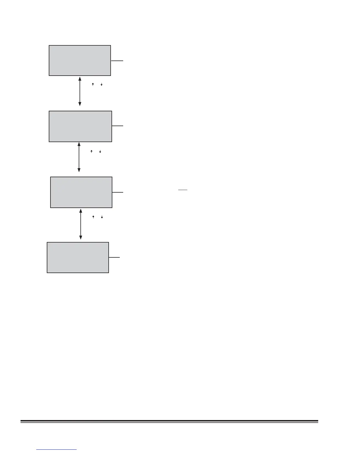
Net T/H Sensors
00.0°F
00.0%rh
T/H Sensor Value Local
Unit 0 of 0 Lead: 1
Press ( ) or ( ) Key
7.2.6.1 Group Sensor Values
This displays the current group temperature and humidity control values transmitted
from the Lead controller. The fi eld below displays the selected control T/H sensor
arrangement (lead, avg, min, max, local) depending upon how the group is set-up.
See Service>Group screens, Section 7.2.6.
The last fi eld shows the unit group address assigned to the controller within the
group and the address of the current lead controller.
Press ( ) or ( ) Key
Group Alarm Setup
1-8: 000 9-16: 000
17-24: 000 25-32: 000
33-40: 000 41-48: 000
49-56: 000
See manual for details
7.2.6.2 Group Alarms
This screen only appears when the controller is wired with additional A/C unit
controllers. It displays bitmask values indicating the alarm conditions that will initiate
a group internal alarm causing the unit to switch over from “Active” to “Unit Off”. See
Service>Group (Alarms Set) earlier in Section 7.2.6.
Group T/H Sensors
Avg 000.0 °F 000.0 %
Min 000.0 °F 000.0 %
Max 000.0 °F 000.0 %
Min Temp 0 Min Hum 0
Max Temp 0 Max Hum 0
Press ( ) or ( ) Key
7.2.6.3 Lead Controller Group Sensors
This screen appears only in the display of the controller that is designated as the Lead
in a multi-unit work group. The lead controller polls the Temperature and Humidity
sensors from all the A/C units in the work group and displays the averaged values. It
also displays the value of the minimum (lowest) temperature sensor and the value of
the minimum humidity sensor in the A/C group and conversely, displays the value of
the maximum (highest) temperature sensor and maximum humidity sensor in the A/C
group. The fi elds at the bottom are the addresses of the controllers in the group that
have the min. (lowest) and max. (highest) temperature and humidity sensor readings.
Group Sensor Status
Unit1 15 Lead Unit 1
Unit1 0 Unit5 0
Unit2 3 Unit6 0
Unit3 0 Unit7 0
Unit4 0 Unit8 0
7.2.6.4 Group Sensor Status
This screen appears only in the display of the controller that is designated as the
Lead in a multi-unit work group. It shows what sensors exist on each A/C unit for the
Lead controller to perform the group sensor averaging calculation. The numbers are
the sums of index values assigned to the sensors as shown in the following key:
1 = Return Temperature Sensor
2 = Return Humidity Sensor
4 = Remote Temperature Sensor
8 = Remote Humidity Sensor
16 = Static Pressure Sensor