STULZ E
2
SERIES CONTROLLER FOR PERIMETER SYSTEMS OPERATION MANUAL
40
operating after pushing the Enter ( ) key or after turning the
unit on with a remote on command.
Airfl ow delay - Time delay for allowing the blowers to reach
adequate speed before the air proving sensor actively monitors
an airfl ow alarm condition.
Shutdown delay - Time delay before unit stops operating
after pressing the Enter (
) key for three seconds or after turning
it off with a "remote off" command.
Recovery time - Time period after startup that temperature
and humidity alarms are masked from signalling nuisance high
or low temperature and humidity alarms.
5.5.7.3 T/H Offset Scaling
T/H Offset Multiplier
Temperature Scale 2.0
Humidity Scale 1.0
Scales effect all the
cut-in, cut-out values
The Service>Options>T/H Offset Multiplier screen allows
the operator to enter a multiplier to apply to scale both the
temperature and humidity cut-in/cut-out offsets. The multipliers
are factored to the system offset values set in the Service menu
(Sections 5.5.1, 5.5. and 5.5.3).
Default Cut-in/Cut-out Offsets
Temp. Cut-in Offset= 2.0 °F; Cut-out Offset= 0.3 °F
Humidity Cut-in Offset= -5.0%; Cut-out Offset= -2.0%
EXAMPLE: Temperature Offset Multiplier
With the default cut-in offset for temperature at 2.0 °F, a
multiplier of 2.0 2 °F = 4 °F. This means the unit will begin
operating in the cooling mode at 76.0 °F (Setpoint 72.0 °F +
Offset 4 °F). Conversely, with the default cut-out offset at 0.3 °F,
the cooling mode will turn off at 72.6 °F.
(Setpoint 72.0 °F + (2.0 Cut-out Offset 0.3 °F))
72.0 °F + 0.6 °F = 72.6 °F
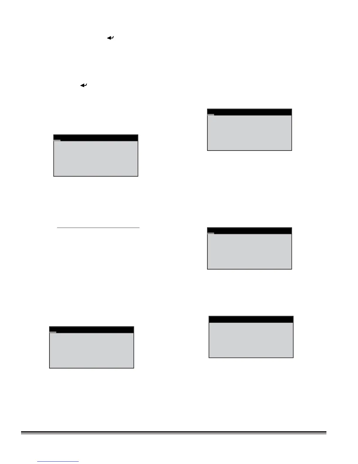
5.5.7.4 Auto Flush Cycle
Auto Flush Cycle
Enable auto fl ush No
For valve under 0.0%
Interval 1 hrs
Duration 0 secs
Number fl ushes 0
The Service>Options/Flush Cycle screen may be used to
enable a periodic fl ushing of the CW, FC or AWS coils with the
control valve in the fully opened position. This is used to remove
any sediment that may have collected while the A/C unit is
actively cooling. (This does not operate if the A/C unit is off or
in standby mode.)
If enabled, a minimum valve opening threshold may be set below
which a periodic fl ush cycle is required. That is, if the control
valve position ever exceeds the percentage entered since the
last fl ush cycle, the scheduled fl ush cycle will be skipped and a
new interval will begin. If the valve does not reach the minimum
open position entered, a fl ush cycle will occur when the interval
since the last fl ush cycle expires. The interval between fl ushes
may be varied from 1 hour to 720 hours (30 days). The duration
of the fl ush cycle may be varied from 30 to 300 seconds. The
number of fl ushes displayed at the bottom of the screen is the
total number of fl ush cycles since the A/C unit was initialized.
5.5.7.5 Barometric Pressure
Barometric Pressure
Select Method:
Elevation
0
The barometric pressure set-up menu is enabled when the
special sensors are selected to be “Airfl ow rate (no GPM)” or
“Calculate GPM” in the Factory>Options>Enb Special Sensors
menu. Select Elevation (default), Manual, Local Sensor, or
Network. The elevation defaults to sea level (0). Manual selects
a fi xed barometric pressure in millibars. Local Sensor selects
an analog input to provide the barometric pressure in millibars.
Network selects a BMS supplied value for the barometric
pressure in millibars.
5.5.7.6 Dual Power
Dual Power Setup
Delay A to B 10s
Delay B to A 10s
Set the switchback
delay to zero to stay
on that power supply.
The Service>Options>Dual Power Setup screens appear only
if the controller is programmed to manage the automatic dual
power transfer sequence. The controller utilizes its onboard
timers for power switch over, not the relay timers in the A/C unit.
This screen allows the delay timers for automatic dual power
switch over to be adjusted.
Dual Power
A_In OK A_Out On
B_In OK B_Out Off
Primary A
Switch Power? No
The next Service>Options>Dual Power screen allows the
status of the dual power sources to be viewed if the controller is
programmed to manage the dual power auto transfer sequence.
The ability to select primary power sources and manually switch
them is available with this screen.
The identifi ers "A" and "B" may be replaced with "Pre" and "Alt"
as an option when the controller is confi gured at the factory. In
such case, power source "A" is termed "Pre" (Preferred); power
source "B" is termed "Alt" (Alternate).