STULZ E
2
SERIES CONTROLLER FOR PERIMETER SYSTEMS OPERATION MANUAL
18
transferred, it will not be allowed to re-start until the “minimum
compressor off” time delay period has elapsed. The A/C system
will operate using the alternate power source until the primary
power source is functionally restored.
When the primary power source is restored, the built-in timers
in the phase monitor relays delay the switch over to ensure the
power is actually stable before activating their output. After the
delay, operation of the A/C system is automatically transferred
back to the primary power source. The system controller must
again re-boot and restart the operating sequence as described
in the previous paragraph. The automatic power transfer time
from one power source to the other is factory set at 10 seconds.
The power transfer timers may be adjusted on the phase monitor
relays in the A/C system electric box. See STULZ addendum
OZU0005, "Operation of Automatic Transfer Switch"for details.
4.10.2 Power Transfer Performed by System
Controller
If the system controller is programmed to manage the dual
power transfer sequence, an optional Constant Contact UPS
module is provided (see Section 2.4.4). It keeps the controller
online while the power transfer sequence takes place. This
allows the controller to continue monitoring sensor input
signals and maintain communications with a BMS for up to one
minute. The controller will not have to reboot due to a power
interruption. It stays operational to indicate an alarm condition
and re-initiate the operating sequence after an automatic power
transfer occurs.
The system controller begins the start-up sequence after
approximately 10 seconds elapsed time which ensures the
“switch to” power source is stable. If the compressor and fans
were running at the time an automatic power transfer takes
place, they will restart as described in Section 3.3. When primary
power is restored, an automatic power transfer sequence occurs
again, returning the A/C system back to the primary power
source. The automatic power transfer delay time may be adjusted
using the system controller in the Service>Options>Dual Power
Setup menu screen (see Section 5.5.7.6).
4.11 Tandem Compressors Operation
The STULZ E
2
controller provided with the A/C unit may be
programmed to effi ciently manage the staging and rotation of
three compressors.
In the example of a system with three compressors, two small
compressors are paired together as one tandem circuit (1a
and 1b) with a shared liquid line and shared discharge line. The
compressor suction and discharge ports are equipped with
back pressure isolation valves so one compressor may operate
independently or both may operate together, as required by the
demand for capacity staging. One larger compressor is also
provided as circuit 2.
The STULZ E
2
controller manages operation of the three
compressors with a unique method of staging to conserve
energy by incrementally matching compressor capacity against
the load. The three compressors are turned on in various
combinations to provide a total of 4 stages of cooling. Each
stage is assigned an offset to the temperature setpoint for
turning the compressors on. The controller turns each stage
on and off as needed based on the temperature setpoint plus
offset values (reference Section 4.5.1.2).
The offsets for each stage may be adjusted in the Service>Cool
menu (see Section 5.5.1.1). The DX Cooling menu display
screens, discussed in Section 5.5.1.1 depict values relevant to
cooling stages rather than to individual compressors.
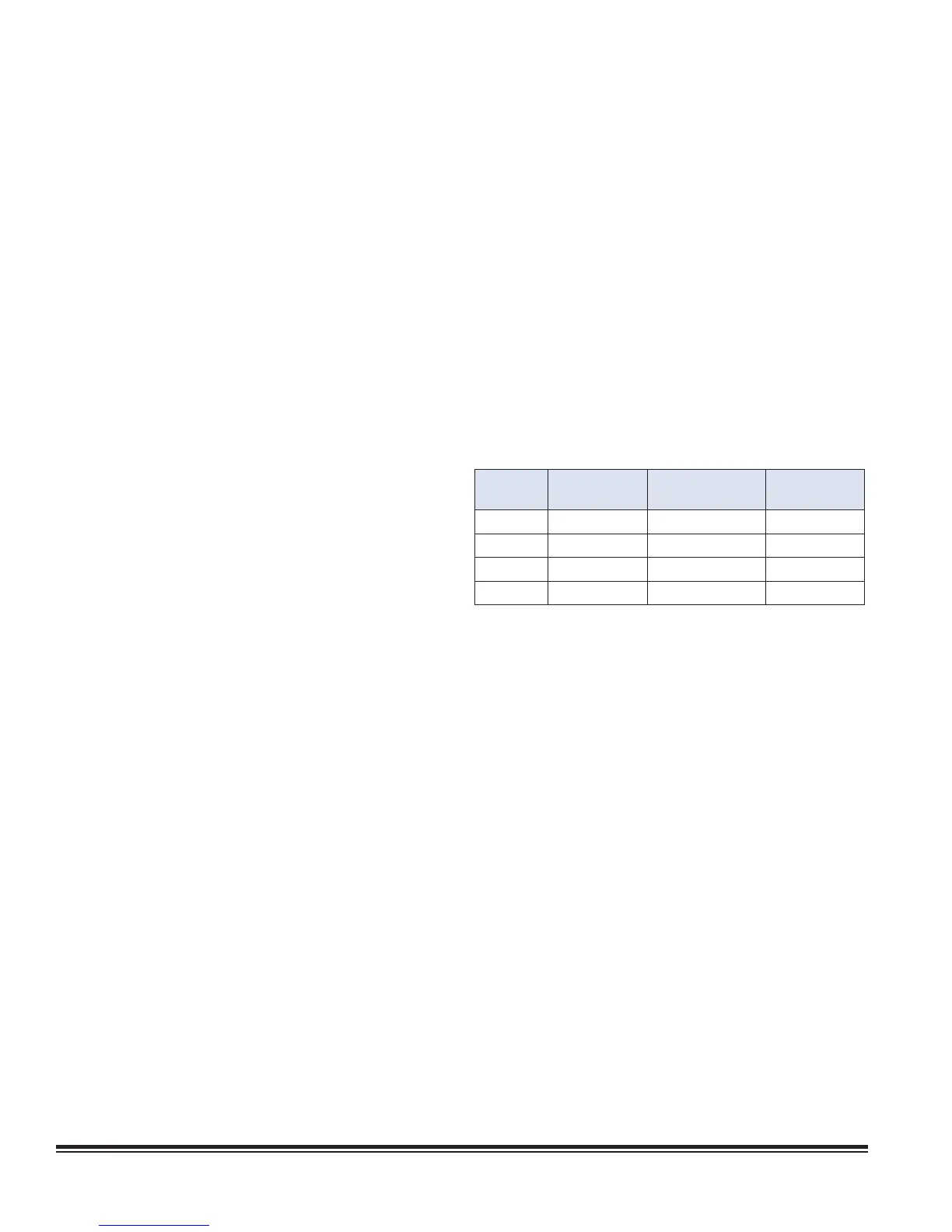
See Table 1 that follows. In the example of a 20 ton (240,000
BTU) system with three compressors, two small (5 ton)
compressors 1a and 1b are paired together as one tandem
circuit with a shared liquid line and shared discharge line.
One large (10 ton) compressor is also provided as circuit 2.
The following table shows how the compressors are staged
according to the capacity demand.
Stage
Cut-in Set-
point Offset
Compressor(s) Capacity
1 +2° F 1a 5 tons
2 +3° F 2 10 tons
3 +4° F 1b+2 15 tons
4 +5° F 1a+1b+2 20 tons
Table 1. Tandem Compressor Operation Example
4.12 Shadow Units
If the unit does not use an external EVD, the STULZ E
2
controller may be used to control up to three units as one with a
common display (set to pLAN address 1724). Shadow control
logic is used specifi cally for STULZ MCS systems which consist
of multiple STULZ CyberONE units integrated together to
operate as a multi-compressor cooling system. Refer to STULZ
Addendum #OCC0061 for detailed information.
The main unit controls the start and stop of the shadow units
and is in the pLAN address range of 18. The one or two shadow
units use pLAN addresses 916 to keep them out of the group
rotation logic. The shadow units follow the main unit in the
rotation process. The shadow units monitor the pLAN status of
the main unit to determine when to start and stop. They are “Off
by Network” when the main unit is not running due to conditions
such as waiting on a manual restart or other event like a BMS
pause. There is an option to allow the shadow units to run if they
see that the main unit is powered down, but the default is for
them to go to “Off by Network”.
The main unit does not normally monitor the shadow units
for starting and stopping, but it does monitor alarms coming
from the units. If the shadow unit is turned off manually or by a
critical alarm to then place it in manual restart mode, the main
unit continues to run and the shadow unit will not restart until