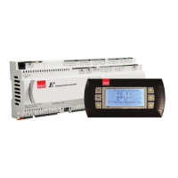
STULZ E
2
SERIES CONTROLLER FOR PERIMETER SYSTEMS OPERATION MANUAL
15
may be set to AWS/FC Primary, DX Primary and DX
only in the Factory>Cool>Energy Savings menus.
1. In AWS/FC Primary, the DX circuits are operational
when the energy savings logic requests the DX logic to
operate or the conditions in section 4.5.1.2 are met. The
CW valve remains fully operational based on the return air
temperature and setpoint.
2. In DX Primary, the DX circuits are operational when the
energy savings logic requests the DX logic to operate or
the conditions in paragraph 4.5.1.2 are met. The CW valve
remains fully operational.
3. The DX Only mode essentially disables the AWS logic.
The DX circuits are operational based on the normal DX
logic and the CW valve is closed at all times.
4.5.2.3 Free Cooling (FC)
The free cooling option (set at the Configuration Level) is
available on Water/Glycol cooled DX systems. In general it is
used to minimize compressor operation during low ambient
conditions for system energy savings. A FC unit utilizes a remote
dry cooler to provide water/glycol coolant to a free-cooling
coil which is located in the AC unit with the DX cooling coil. The
operation of the FC logic is identical in all other respects to the
AWS logic.
NOTE
The call for DX cooling is not disabled from its normal
logic when the AWS/FC option is selected. When
the return air temperature rises above its threshold
(setpoint plus 3.0 °F as a default) to start DX cooling
or dehumidifi cation, the DX logic is enabled regardless
of the state of the FC logic.
4.5.3 Heating
Electric resistance heating element(s) are utilized for heating
the process air. The controller sends digital output signal(s) to
turn the element(s) on or off as required to reach setpoint. Up
to 3 stages of electric heat may be provided with individually
selectable setpoints.
Proportional control for Silicon Controlled Rectifier (SCR)
heating may be provided as an option for more precise control
of heating energy. With this option the controller transmits
analog output signals to the SCR's that are proportional to the
demand for heat.
4.5.4 Humidifying
If this option is selected, an on-board steam humidifi er may be
turned on or off by the controller to maintain relative humidity to
a control setpoint. Once the controller enables humidifi cation,
the humidifi er will operate at 100% capacity until the humidity
setpoint is reached. An on-board control module manages the
humidifi er operation, i.e. humidity production, fi ll cycles, drain
cycles.
4.5.4.1 Humidifying With Proportional Control
If this option is selected, proportional control of humidifi cation
may be provided as an option for even more precise control of
the relative humidity. With this option the controller transmits
an analog output signal to the humidifi er that is proportional to
the demand for humidifi cation.
4.5.5 Dehumidifying
When dehumidification is called for the blower speed
automatically changes to the dehumidification fan speed
setting. The controller will operate the system in the cooling
mode to strip moisture from the air. If the system is equipped with
dual compressors, only one compressor stage will operate when
in the dehumidifi cation mode unless the system is equipped
with a remote condenser and enabled for hybrid control (see
Section 4.4.1). In a CW system, the control valve is factory set
to be fully opened for dehumidifi cation provided the inlet water
temperature is 45 °F or cooler. It may be set to be less than fully
open for dehumidifi cation, if desired, in the Service>Humidity
menu (see Section 5.5.3).
The system will remain in the cooling mode until the actual
relative humidity (or dewpoint) reaches the control setpoint
plus the dehumidifi cation cut-out offset. If room temperature
drops below the low temperature cut-out setpoint for the
dehumidification mode (temperature setpoint minus 4°F
default), cooling operations will be stopped (see Figure 6).
4.5.5.1 Reheat
During dehumidifi cation the space temperature may decrease
below the desired value due to the cooling being run at
full output. When the temperature decreases below the
temperature setpoint plus the reheat cut-in offset, the system
will enter the reheat mode. While in this mode Reheat will be
displayed at the bottom of the Main screen instead of Heat to
alert the user that the system is in the dehumidifi cation mode
and reheat is required. Control for reheat will follow the same
control algorithms as described in the Heating Section 4.5.3
and the available heaters will be activated as required.
If the temperature drops below the dehumidification low
temperature cut-out setpoint, dehumidification will be
stopped but the reheat mode remains on until the temperature
setpoint plus reheat cut-out offset is reached. Reheat during
dehumidifi cation can utilize either the return air temperature
sensor or the remote air temperature sensor as the basis for
control.
4.6 Airfl ow/Fan Speed Control
In DX based systems, the STULZ E
2
controller treats the EC
fan as a 3-speed fan (Min., Max. and Dehumidifi cation). The
minimum fan speed is used whenever the A/C unit has no
heating or cooling operations running. The maximum fan speed
setting is used during times when the A/C unit is heating, cooling
or humidifying. When the system is in the dehumidifi cation
mode, the fan speed is reduced to the dehumidifi cation fan

 Loading...