STULZ E
2
SERIES CONTROLLER FOR PERIMETER SYSTEMS OPERATION MANUAL
54
The terminal for controller 1 is always addressed 32; the terminal for controller 2 is always addressed 31, and so on such that the
sum of the controller address number and the terminal address number always equals 33. Therefore, when viewing controller number
1, its terminal address will be 32. When viewing controller number 2, its terminal address will be 31, and so on.
Press a ( ) or ( ) arrow key to display the next screen showing the version of the fi rmware residing in the terminal.
To exit the Network Status menu, press ( ).
The next step is to access the Service>Group screens used to confi gure the work group parameters (Section 7.2.6).
7.2.6 Confi gure Work Groups
Enter the Service>Group menu screens when multiple A/C units are grouped. These menu screens allow grouping parameters
(duty, rotation, offsets, etc) to be defi ned for the A/C units in the work group. These screens should be accessed after setting up
the work groups (Section 7.2). The Service>Group menu screens may be accessed from the main screen by pressing the Prg key
and scrolling through the menu selections until the word SERVICE appears in the center of the screen.
MAIN MENU
Control
SERVICE
Factory
Press the Enter ( ) key twice and a screen will appear to enter the password
for the Service level.
Once the Service level password is accepted, press Enter
( ) to call up the
menu screens. From here, press the Up ( ) ) or Down( )arrow keys to scroll
through the Service menu selections.
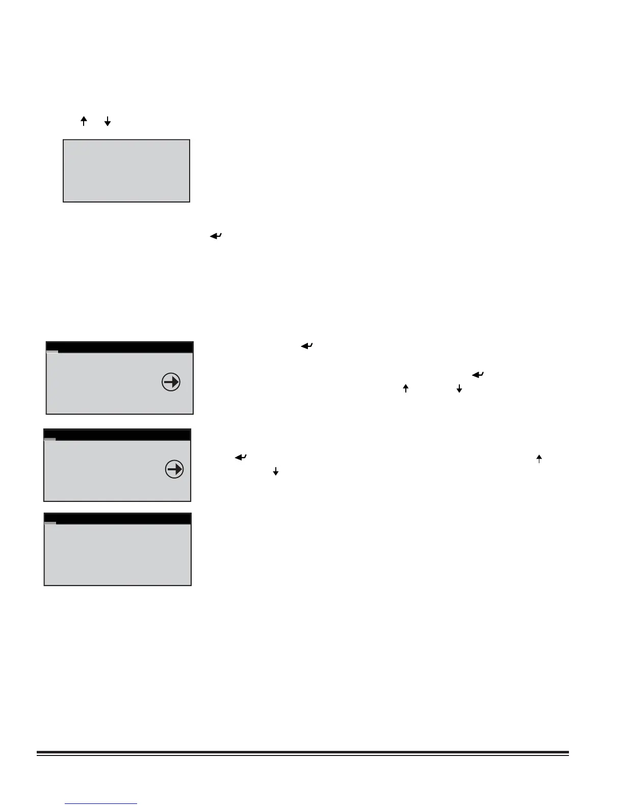
SERVICE MENU
BMS Comm
GROUP
Save Cfg
When the word GROUP appears in the center of the screen, press the Enter (
) key to access the Service>Group menu screens. From here, use the Up ( )
or Down ( ) arrow keys to scroll through the Service>Group menu selections.
Group Confi g
Unit ACTIVE
Total in Network 3
Min Number Active 1
Min Number Assist 1
Lead Unit 1
Service>Group>Group Confi g (Screen 1)
See table below.
NOTE: Standby units are added to the number appearing in the Total in
Network fi eld although no fi eld id provided in this screen indicating the
number of standby units that are part of the group. To determine the number of
standby units, subtract Min Number Active + Min Number Assist
from Total in Network. In the example shown there is one standby unit.
pGD1 V1.7
Feb 28 2006
HW:A
Firmware Version