STULZ E
2
SERIES CONTROLLER FOR PERIMETER SYSTEMS OPERATION MANUAL
35
5.5 Service Menu
MAIN MENU
Control
SERVICE
Factory
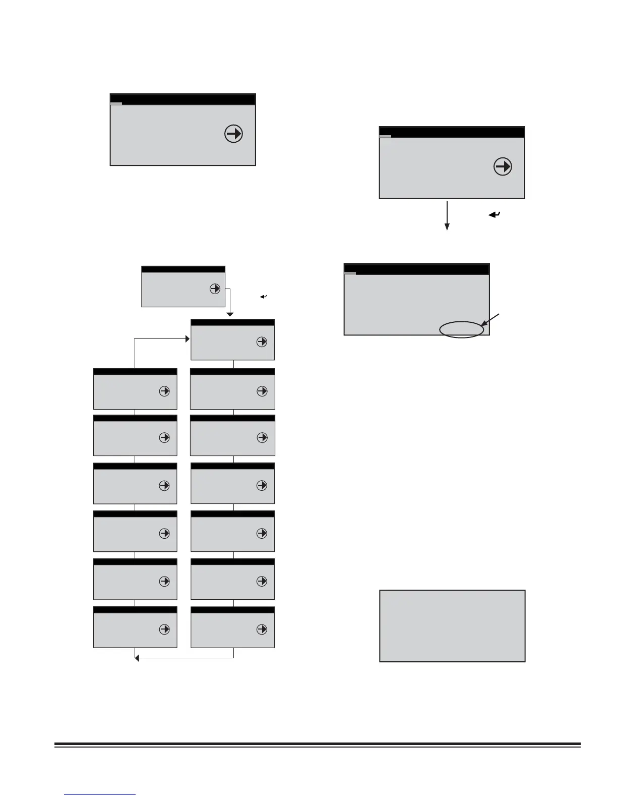
The Service menu screens (Figure 8) allow the user to enter
cut-in and cut-out values, calibrate the system control sensor(s),
save and restore parameters and view the event log. The Service
menu may be entered and programmed by the user via the
password menu (requires level 2 password). Once password
access is granted, the user may access the service menu
screens.
-- 5.5.1
-- 5.5.2
-- 5.5.3
-- 5.5.4
-- 5.5.5
-- 5.5.6
-- 5.5.7
MAIN MENU
Control
SERVICE
Factory
SERVICE
Factory
COOL
Heat
SERVICE
Heat
HUMID
Alarms
SERVICE
Humid
ALARMS
Sensors
SERVICE
Alarms
SENSORS
Blower
SERVICE
Sensors
BLOWER
Options
SERVICE
Blower
OPTIONS
Digital In
Press Enter ( )
Key
5.5.13 --
5.5.12 --
5.5.11 --
5.5.10 --
5.5.9 --
5.5.8 --
SERVICE
Options
Digital In
Run Hours
SERVICE
Digital In
RUN HOURS
BMS Comm
SERVICE
Run Hours
BMS COMM
Group
SERVICE
Group
SAVE CFG
Factory
SERVICE
Save Cfg
FACTORY
Cool
SERVICE
Cool
HEAT
Humid
SERVICE
BMS Comm
GROUP
Save Cfg
5.5.1 Cool
The Service>Cool menu screens differ depending upon
whether the A/C unit is confi gured for DX operation and/or
CW/WG/AWS operation.
SERVICE
Blowers
COOL
Heat
Press Enter ( ) Key
5.5.1.1 DX Cooling Screens
Stage 1 Cooling
Cut In Offset: 2.0°F
Cut Out Offset: 0.3°F
STATUS---------------
Temp:73.7°F Set:72.0°F
Stage 1:off M: 1.0
Offset Multiplier
See Sect. 5.5.7.3
If the A/C unit is confi gured with compressor(s), the cut-in/
cut-out offsets for each compressor stage may be adjusted
from the Service>Cool menu. The offset values are added to
the temperature setpoint and establish the temperatures for the
compressor to turn on (Cut-in) and off (Cut-out). This screen also
displays the current air temperature and setpoint temperature.
The On/Off status of the compressor (Stage 1) is shown at the
bottom of the screen along with the offset multiplier (M). The
offset multipliers may be set in the Service>Options>T/H
Scaling menu screen (see Section 5.5.7.3).
If the A/C unit is confi gured for operation as a dual compressor
or tandem compressor system, additional screens are provided
for viewing and adjusting parameters for the additional stages.
Ordinarily, A/C units equipped with multiple compressors
stage the operation of the compressors based on rising air
temperature. The compressors rotate after each run cycle.
A Redundant Set-up screen appears next for units equipped
with dual compressors (STULZ models VFS and CFS), if the
unit is confi gured for redundant operation.
Redundant Setup
Number of Days 0
Hour of Day 0
Current Lead 1
It allows the operator to adjust the number of days for switching
the lead cooling circuit duty and select an hour of the day for
this to occur. The current lead circuit may also be changed at
the display.
Figure 8. Service Menu Selections