STULZ E
2
SERIES CONTROLLER FOR PERIMETER SYSTEMS OPERATION MANUAL
53
P:02 Adr Priv/Shared
Trm1 31 Pr
Trm2 None --
Trm3 None -- Ok?No
Terminal Confi guration
Next , press the Up (
), Down ( ) and Enter ( ) keys simultaneously. Reconfi gure the terminal address following the steps in Section
7.2 again. This time set the terminal address to match the corresponding controller I/O board address.. If the controller is assigned
address 2, then the corresponding terminal address should be set to 31 as shown in the table on the preceding page. If the next
controller is assigned address 3, the corresponding terminal should be set to 30.
After setting the correct terminal address, press the (
) key once to confi rm the selection. A message NO LINK will appear. At
this point, the terminal has been set with the correct address for the controller and the controller has been set for the terminal, but
now they need to be assigned to each other.
7.2.3 Assign the Terminal to the Controller
1. Access the Terminal Address Confi guration screen again using the Up ( ), Down ( ) and Enter ( ) keys.
2. Press the ( ) key until the cursor moves to the fi eld I/O board address.
3. Using the ( ) ( ) keys, enter the address (1 – 8) for the controller I/O board.
4. Press the ( ) key twice to display the Terminal Confi guration screen.
5. Here too, the ( ) key moves the cursor from one fi eld to the next, and the ( ) ( ) keys change
the value of the current fi eld. The fi eld P:0_ depicts the pLAN address (1 – 8) assigned to
the I/O board. In the example shown, the controller has been assigned address 2.
6. Press the ( ) key to move to the fi eld Trm1 xx. The fi eld represents the address of the
terminal associated with the controller. Using the ( ) ( ) keys enter the address (25 – 32) of the terminal assigned to the con-
troller (I/O board). In the example shown, address 31 has been entered for the fi rst A/C unit added to the group.
7. The Priv/Shared column indicates the type of terminal. The workgroup is setup using private terminals. Do not change the value
(Pr). Press the ( ) key to move to the last fi eld
8. Select the fi eld Ok?No, choose Yes using the ( ) ( ) keys and confi rm by pressing ( ) to save the data and exit the group
set-up procedure.
9. Referring to the wiring diagram provided with the A/C units, interconnect the units together with the pLAN cable(s) provided.
7.2.4 Fault messages
If the terminal detects the status of the I/O board it is associated with is off-line, the display shows the message:
I/O Board xx fault. If this appears, check the Signal LEDs on the controller (see Figure 3) for an error signal. See Section
8.4 for guidelines on analyzing the signal LED’s.
On the other hand, if the terminal receives no signal from the network, the display shows the following message:
NO LINK. If this appears, check the pLAN cables and ensure they are connected properly. Also, check the addressing (refer to
Section 7.2).
7.2.5 Displaying the Network Status and Firmware Version
Once each A/C unit is confi gured with its new controller and terminal pLAN address, the entire network set up may be examined.
Press the group set up keys ( ) ( ) ( ) together as done to access the Address Confi guration screen but continue holding after
the Address Confi guration screen appears for at least 5 seconds until the Network Status (NetSTAT) screen appears.
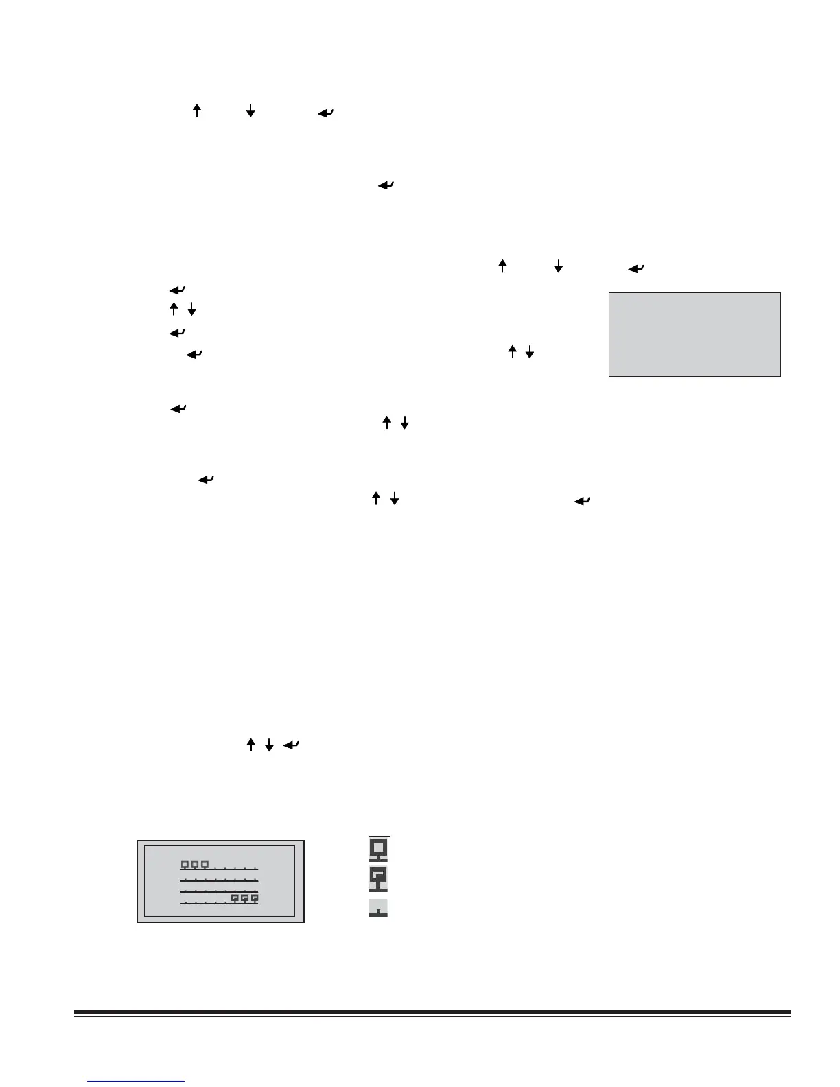
The Network Status screen, shown below, provides overview of the pLAN group indicating which and how many devices are
connected and the corresponding pLAN addresses.
Network Status
NetSTAT Term:32
1 8
9 16
17 24
25 32
Press Enter to quit
Key:
: Controllers (I/O Boards) active in network
: Terminals active in network
: No device connected
The example shown represents:
Controllers active in network, addresses: 1, 2, 3. ...
Terminals active in network, addresses: 30, 31, 32.