ME(H4SO)-66
MECHANICAL
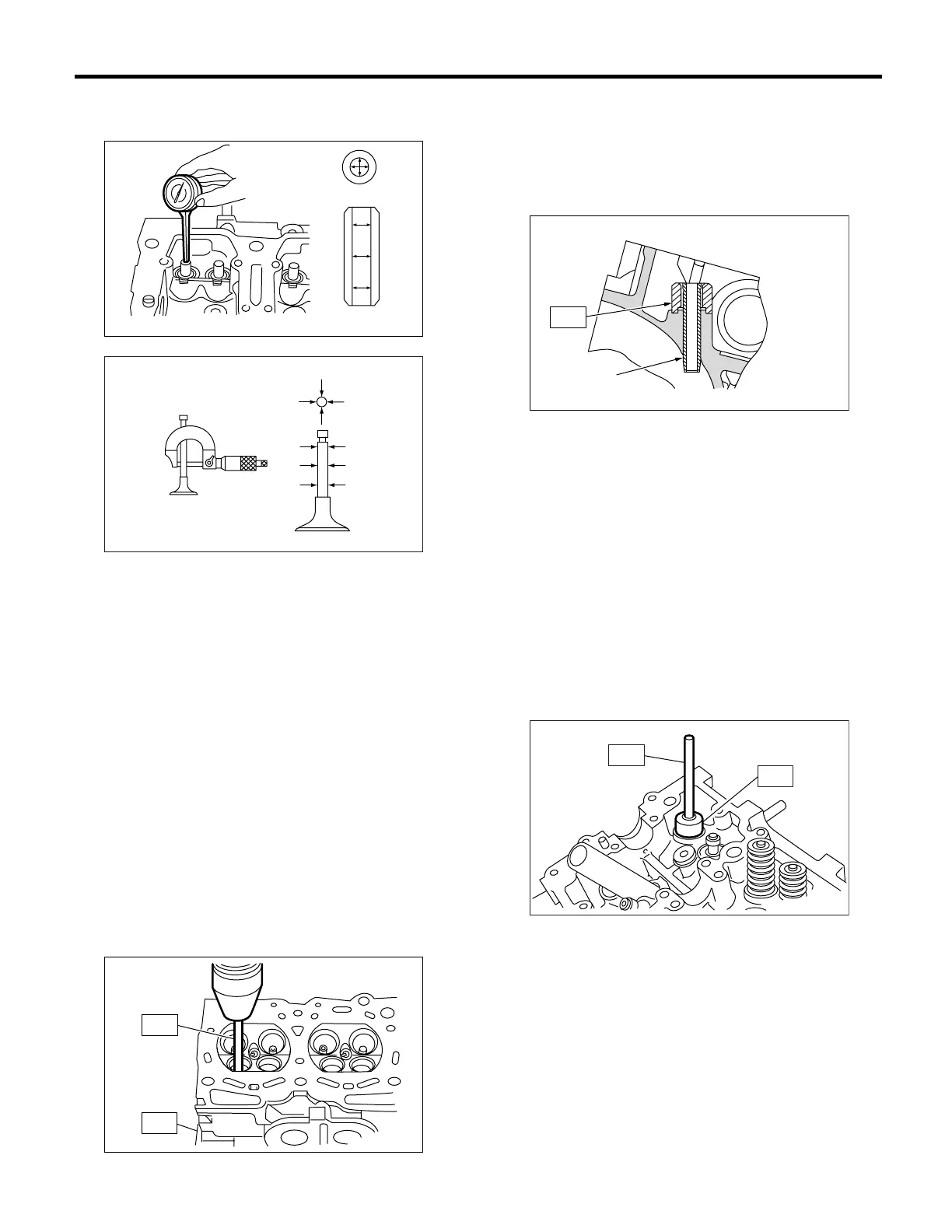
Cylinder Head Assembly
Limit
0.15 mm (0.0059 in)
2) If the clearance between valve guide and stem
exceeds the limit, replace the valve guide or valve
itself whichever shows greater amount of wear.
See the following procedure for valve guide re-
placement.
Valve guide inner diameter:
6.000 — 6.012 mm (0.2362 — 0.2367 in)
Valve stem outer diameters:
Intake
5.950 — 5.965 mm (0.2343 — 0.2348 in)
Exhaust
5.945 — 5.960 mm (0.2341 — 0.2346 in)
(1) Place the cylinder head on ST1 with the
combustion chamber upward so that valve
guides enter the holes in ST1.
(2) Insert the ST2 into valve guide and press it
down to remove valve guide.
ST1 498267800 CYLINDER HEAD TABLE
ST2 499767200 VALVE GUIDE REMOVER
(3) Turn the cylinder head upside down and
place ST as shown in the figure.
Intake side:
ST 499767700 VALVE GUIDE ADJUSTER
Exhaust side:
ST 499767800 VALVE GUIDE ADJUSTER
(4) Before installing new oversize valve guide,
make sure that neither scratches nor damages
exist on the inside surface of valve guide holes
in cylinder head.
(5) Put new valve guide, coated with sufficient
oil, in the cylinder, and then insert the ST1 into
valve guide. Press in until the valve guide upper
end is flush with the upper surface of ST2.
ST1 499767200 VALVE GUIDE REMOVER
Intake side:
ST2 499767700 VALVE GUIDE ADJUSTER
Exhaust side:
ST2 499767800 VALVE GUIDE ADJUSTER
(6) Check the valve guide protrusion.
Valve guide
ME-00288
ME-00289
X
Y
ME-00290
ST2
ST1
(A) Valve guide
(A)
ME-00291
ST
ST2
ME-00292
ST1
 Loading...