ME(H4SO)-62
MECHANICAL
Cylinder Head Assembly
20.Cylinder Head Assembly
A: REMOVAL
1) Remove the V-belt. <Ref. to ME(H4SO)-43, RE-
MOVAL, V-belt.>
2) Remove the crankshaft pulley. <Ref. to
ME(H4SO)-45, REMOVAL, Crankshaft Pulley.>
3) Remove the timing belt cover. <Ref. to
ME(H4SO)-47, REMOVAL, Timing Belt Cover.>
4) Remove the timing belt assembly. <Ref. to
ME(H4SO)-48, REMOVAL, Timing Belt Assem-
bly.>
5) Remove the camshaft sprocket. <Ref. to
ME(H4SO)-53, REMOVAL, Camshaft Sprocket.>
6) Remove the intake manifold. <Ref. to
FU(H4SO)-16, REMOVAL, Intake Manifold.> or
<Ref. to FU(H4SOw/oOBD)-16, REMOVAL, Intake
Manifold.>
7) Remove the bolt which installs the A/C compres-
sor bracket on cylinder head.
8) Remove the valve rocker assembly. <Ref. to
ME(H4SO)-56, REMOVAL, Valve Rocker Assem-
bly.>
9) Remove the camshaft. <Ref. to ME(H4SO)-58,
REMOVAL, Camshaft.>
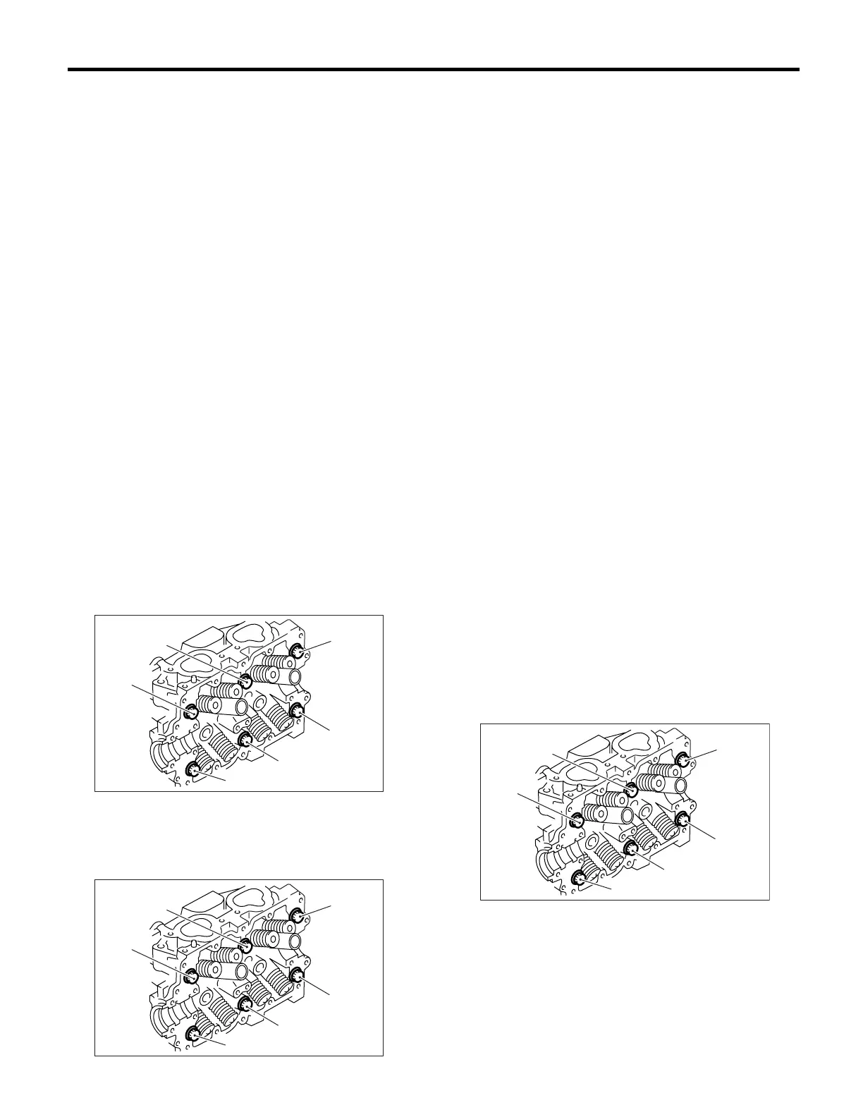
10) Remove the cylinder head bolts in alphabetical
sequence shown in the figure.
NOTE:
Leave the bolts (a) and (c) engaged by three or four
threads to prevent cylinder head from falling.
11) While tapping the cylinder head with a plastic
hammer, separate it from cylinder block.
12) Remove the bolts (a) and (c) to remove cylinder
head.
13) Remove the cylinder head gasket.
CAUTION:
Do not scratch the mating surface of cylinder
head and cylinder block.
14) Similarly, remove the right side cylinder head.
B: INSTALLATION
1) Install the cylinder head and gaskets on cylinder
block.
CAUTION:
• Use new cylinder head gaskets.
• Be careful not to scratch the mating surface
of cylinder block and cylinder head.
2) Tighten the cylinder head bolts.
(1) Apply a coat of engine oil to the washers and
bolt threads.
(2) Tighten all bolts to 29 N·m (3.0 kgf-m, 22 ft-
lb) in alphabetical sequence.
Then tighten all bolts to 69 N·m (7.0 kgf-m, 51 ft-
lb) in alphabetical sequence.
(3) Back off all bolts by 180° first; back them off
by 180° again in reverse order of installation.
(4) Tighten the bolts (a) and (b) to 34 N·m (3.5
kgf-m, 25 ft-lb) in reverse order of installation.
(5) Tighten the bolts (c), (d), (e) and (f) to 15
N·m (1.5 kgf-m, 11 ft-lb).
(6) Tighten all bolts by 80° to 90° in alphabetical
sequence.
CAUTION:
Do not tighten bolts more than 90°
°°
°.
(7) Further tighten all bolts by 80° to 90° in al-
phabetical sequence shown in figure below.
CAUTION:
Ensure that the total “re-tightening angle” [in
the former two steps], do not exceed 180°
°°
°.
3) Install the camshaft. <Ref. to ME(H4SO)-59, IN-
STALLATION, Camshaft.>
4) Install the valve rocker assembly. <Ref. to
ME(H4SO)-56, INSTALLATION, Valve Rocker As-
sembly.>
5) Install the A/C compressor bracket on cylinder
head.
ME-00278
(c)
(b)
(f)
(d)
(a)
(e)
ME-00278
(c)
(b)
(f)
(d)
(a)
(e)
ME-00279
(c)
(b)
(f)
(d)
(a)
(e)