ME(H4SO)-85
MECHANICAL
Cylinder Block
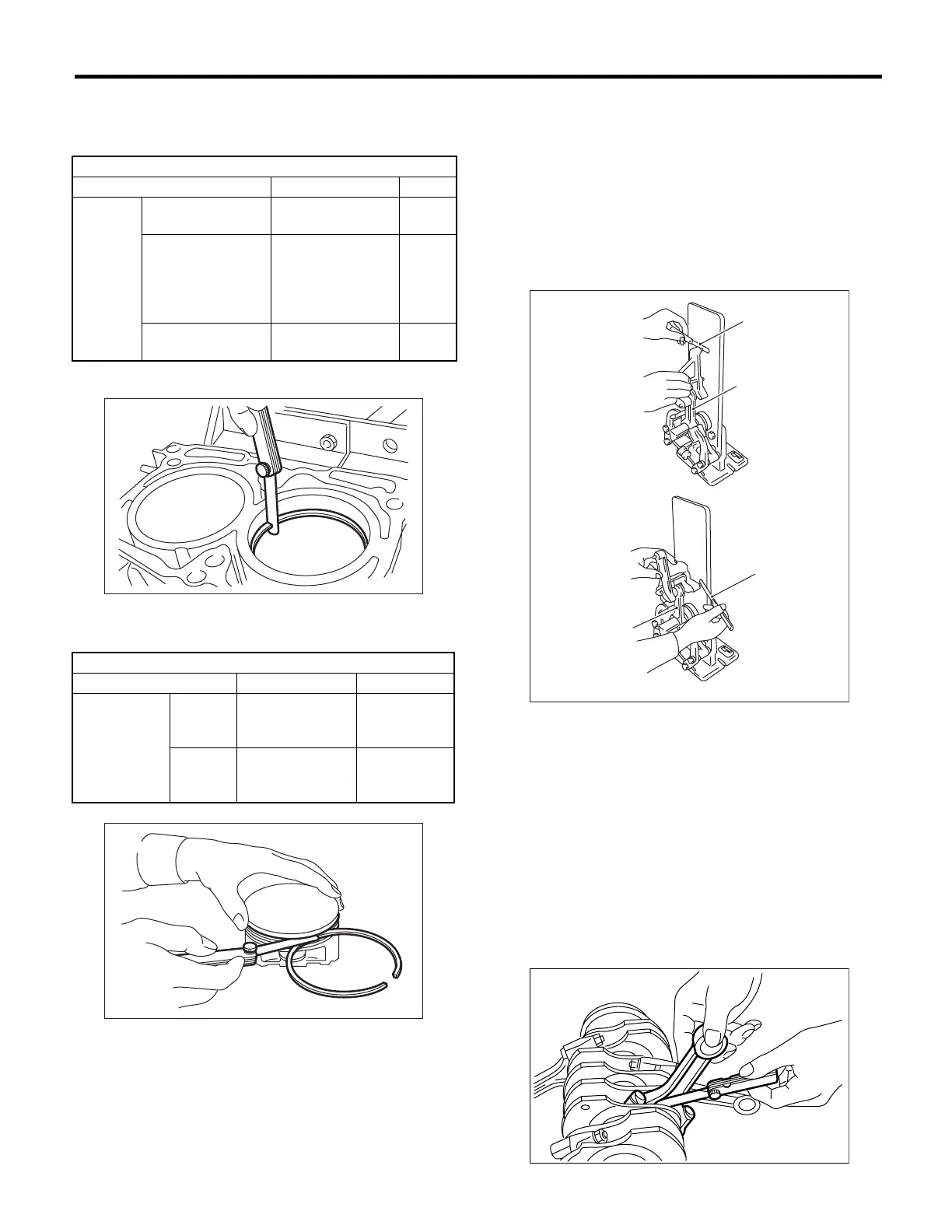
3) Squarely place the piston ring and oil ring in cyl-
inder, and then measure the piston ring gap with a
thickness gauge.
*: 2.0 L model
4) Measure the clearance between piston ring and
piston ring groove with a thickness gauge.
5. CONNECTING ROD
1) Replace the connecting rod, if the large or small
end thrust surface is damaged.
2) Check for bend or twist using a connecting rod
aligner. Replace the connecting rod if the bend or
twist exceeds the limit.
Limit of bend or twist per 100 mm (3.94 in) in
length:
0.10 mm (0.0039 in)
3) Install the connecting rod fitted with bearing to
crankshaft, and then measure the side clearance
(thrust clearance). Replace the connecting rod if
the side clearance exceeds the specified limit.
Connecting rod side clearance:
Standard
0.070 — 0.330 mm (0.0028 — 0.0130 in)
Limit
0.4 mm (0.016 in)
Unit: mm (in)
Standard Limit
Piston
ring gap
Top ring
0.20 — 0.35
(0.0079 — 0.0138)
1.0
(0.039)
Second ring
0.35 — 0.50
(0.0138 — 0.0197)
0.40 — 0.50
(0.0157 —
0.0197)*
1.0
(0.039)
Oil ring rail
0.20 — 0.50
(0.0079 — 0.0197)
1.5
(0.059)
Unit: mm (in)
Standard Limit
Clearance
between pis-
ton ring and
piston ring
groove
Top ring
0.040 — 0.080
(0.0016 —
0.0031)
0.15 (0.0059)
Second
ring
0.030 — 0.070
(0.0012 —
0.0028)
0.15 (0.0059)
ME-00177
ME-00178
(A) Thickness gauge
(B) Connecting rod
(A)
(A)
(B)
(B)
ME-00179
ME-00180












 To Next Page