LU(H4SO)-13
LUBRICATION
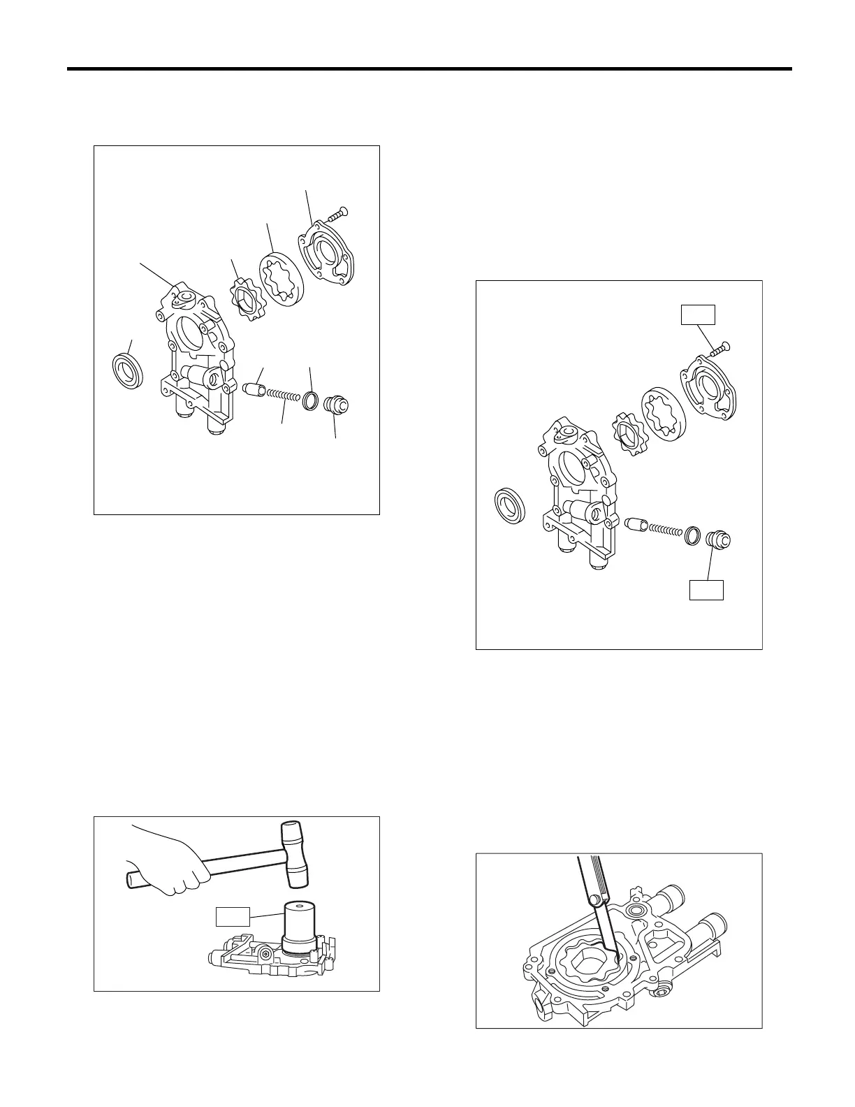
Oil Pump
CAUTION:
Before disassembling the oil pump, remove the
relief valve.
D: ASSEMBLY
1) Install the front oil seal by using ST.
ST 499587100 OIL SEAL INSTALLER
NOTE:
Use a new oil seal.
2) Apply a coat of engine oil to the inner and outer
rotors.
3) Install the inner and outer rotors in their original
positions.
4) Install the oil relief valve and relief valve spring
and plug.
NOTE:
Use a new gasket.
5) Install the oil pump cover.
Tightening torque:
T1: 5 N·m (0.5 kgf-m, 3.6 ft-lb)
T2: 44 N·m (4.5 kgf-m, 32.5 ft-lb)
E: INSPECTION
1. TIP CLEARANCE
Measure the tip clearance of rotors. If clearance ex-
ceeds the limit, replace the rotors as a matched set.
Tip clearance:
Standard
0.04 — 0.14 mm (0.0016 — 0.0055 in)
Limit
0.18 mm (0.0071 in)
(A) Oil seal
(B) Oil pump case
(C) Inner rotor
(D) Outer rotor
(E) Oil pump cover
(F) Relief valve
(G) Relief valve spring
(H) Plug
(I) Gasket
LU-00020
(E)
(D)
(C)
(B)
(A)
(F)
(G)
(I)
(H)
LU-00021
ST
LU-00022
T1
T2
LU-00023