SummaCut Series Cutters User’ s Manual
General Information 1-10
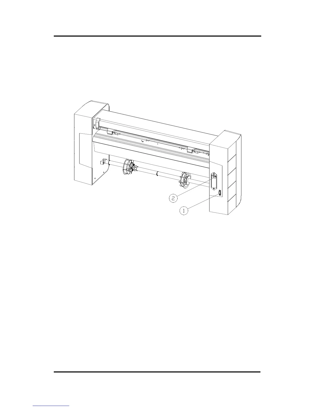
1.4. REAR PANEL COMPONENTS
In order to get acquainted with your SummaCut cutter, read the following
description of the rear panel components. Figure 1-1 shows the location of the
main components.
FIGURE 1-1:
SUMMACUT SERIES REAR VIEW
1. RS-232-C Port.- This DB-9P connector provides the communication link
between the cutter and a host computer. It allows bidirectional
communication between the host computer and the cutter.
2. Power Entry Module.- The fuse box, the voltage select board and the AC
power cord receptacle are located in the power entry module.
The power-up procedure is explained in detail in Section 1.6.
For information on the conversion of the cutter’ s operating voltage, see
Section 3.2.