User Manual 5 Electrical Connection
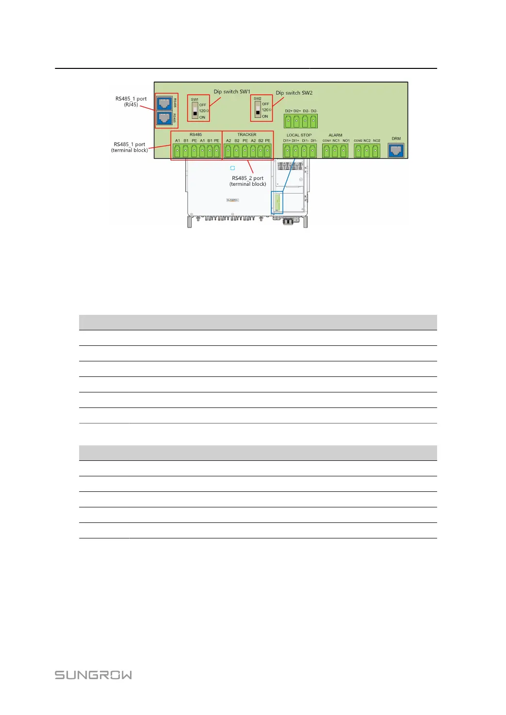
The inverter is equipped with two groups of RS485 communication port for external commu
nication connection, which are RS485_1 port and RS485_2 port.
The port RS485_1 is used to connect Logger, so as to implement data exchange with PC or
other monitoring devices. Terminal definitions of the port are as follows:
table 5-3 RS485_1 port terminal definition (Terminal block)
No Definition
A1 RS485 A IN, RS485A differential signal+
B1 RS485 B IN, RS485B differential signal-
PE GND, shielded earthing point
A1 RS485 A OUT, RS485A differential signal+
B1 RS485 B OUT, RS485B differential signal-
PE GND, shielded earthing point
table 5-4 RS485_1 port terminal definition (RJ45)
No Definition
PIN1~2 N/A
PIN3 RS485 B, RS485B differential signal-
PIN4~5 N/A
PIN6 RS485 A, RS485A differential signal+
PIN7~8 N/A
The terminal block interface and RJ45 interface have the same function with different wiring
manner. Select either interface for cable connection.
When multiple inverters are connected in the RS485 daisy chain, a 120Ω terminating resistor
can be connected between the A and B communication cables through the RS485-dip switch,
to ensure communication quality.
59