CHAPTER FIVE
Table 5-2
Trouble Symptoms/Solutions (Continued)
Symptom Possible Problem and Solution
Unit fails to operate at power up and after
Manual Reset performed.
Possible failure or improper installation of an
Option Assembly. Remove Option
Assembly(s) and perform a Manual Reset.
Possible bad LCD Display. LCD Display must
respond to Microprocessor to allow unit to
operate. Replace LCD Display.
Unit will not Translate or Sync to the Code
input at J8.
Possibly wrong input code or filter selected.
Check Input Code selected.
Possible AGC/Code Stripper problem.
Check TP4 for a CMOS level square wave at
the rate of the selected Code Input. Check TP3
for a ∅C signal.
Check the AGC/Stripper circuitry (TP2) if
there are no signals at TP4 and TP3.
Table 5-3
J32 Power Connector
Pin Assignments
J32 Pin Signal
1 +12 Volts
2 +5 Volts
3 +5 Volts
4 Ground
5 Ground
6 -12 Volts
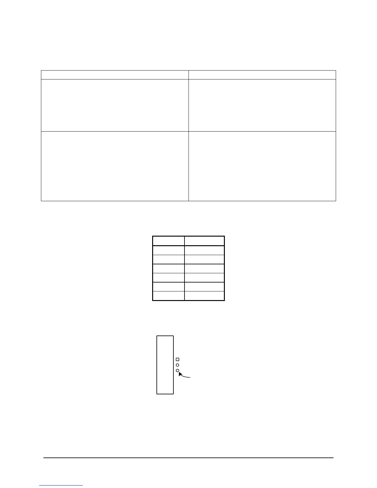
Figure 5.3.3
A1
PIN 3 +5 VOLTS
5-6 TM7000 TymMachine TCG/T (Rev D) Symmetricom, Inc.
 Loading...