CHAPTER THREE
OPERATION
3.0 INTRODUCTION
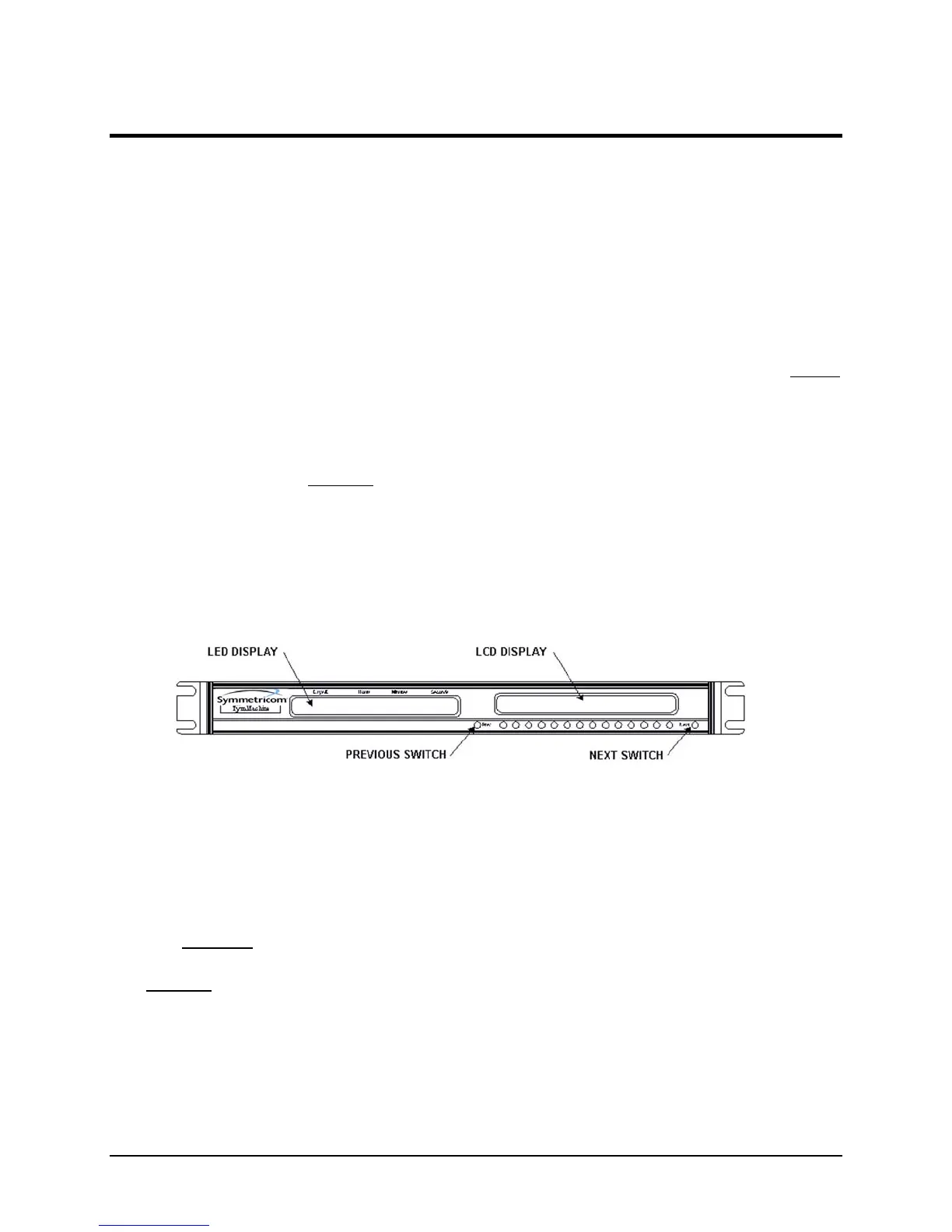
The TymMachine TM7000 features two independent displays, an LED Time display and a LCD
Display (MENU) of instrument function and user selections. Immediately below the LCD
Display are sixteen push-button switches. The switches at either end are used to select the next
or previous menu. The remaining fourteen switches are used to make selections from the menu.
In many cases when a selection is made, the menu is automatically changed to the next menu. If
the operator wishes to retain the previously made selection, he may simply press the NEXT
switch. Once made, a selection remains in memory indefinitely until changed by the operator.
3.1 CONTROLS AND INDICATORS
With the exception of the POWER switch (located on the rear panel Power Entry Module), all of
the normal operating controls of the TM7000 are located on the front panel. Their purposes and
functions are described in the following paragraphs.
Note: The outputs, jumper selections, potentiometers etc. described in this Operation
Chapter are derived from and located on the Synchronized Time Code Generator (STCG),
Assembly 100007.
TM7000 Front Panel
Figure 3.1
3.2 CONTROLS
The following is an explanation of the controls used in this unit:
3.2.1 POWER SWITCH
The
POWER Switch is rocker type switch, located on the rear panel Power Entry Module of the
unit. It controls application of AC power to the unit. The internal battery for backup time
keeping is not controlled with this switch.
Symmetricom, Inc. TM7000 TymMachine TCG/T (Rev D) 3-1
 Loading...