THEORY OF OPERATATION
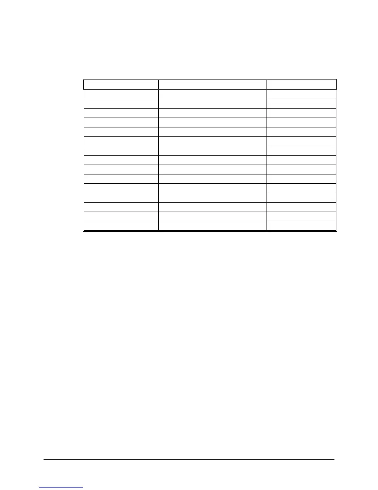
Table 4-2
Rear Panel Connector J3 Signals
Connector J3 Pin Signal Source
1 Pulse Rate 1KPPS Generator
2 Pulse Rate 100PPS Generator
3 Pulse Rate 10PPS Generator
4 Pulse Rate 1PPS Generator
5 Carrier Translator
6 Carrier /10 Translator
7 Carrier /100 Translator
8 Carrier 1K Translator
9 Ground Generator
10 IRIG DC Level Shift Output Generator
11 LOSS Translator
12 ERR Translator
13 Not Used N/A
14 Not Used N/A
15 Not Used N/A
4.8 [7] (TRANSLATOR AGC)
The regulator shown at A1 is used to generate the – 5 Volt power for the Translator Assembly.
This logic contains the input amplifier AGC and the code strippers required to normalize the
input and to derive the necessary clock signals for the decoder.
The AGC amplifier is wide band to make the unit operational where variations of input signal
frequency as well as amplitude are experienced such as in Tape Search applications.
Generally if a Translator is used as a single purpose unit such as to only translate code at a single
rate and display it, the AGC circuits can be narrow band. To make the unit more adaptable to
different types of applications, we have provided a 100 mV to 10 Volt dynamic range and a
frequency response of 30Hz to 2MHz. The circuit does not require adjustment over this range.
Symmetricom, Inc. TM7000 TymMachine TCG/T (Rev D) 4-11
 Loading...