CHAPTER FOUR
data, or read data, respectively to the Backup Clock. When writing to the LED Display, W/ is
used to store data into the display driver with the digit address provided by VCOM PB4-PB6.
PB7 provides decimal point information. The Seconds digit is written by LDUS/. VCOM, PB4,
is a register select to the LCD Display. VCOM, PB5, functions as a read/write control for the
LCD Display. As previously mentioned, ENL is used to clock transfers to the LCD Display.
U52 and part of U26 are used to buffer output signals.
CAUTION
The TymMachine will not operate without a functioning LCD Display connected. The LCD
Display is a Microprocessor based subsystem, which must interact with the Generator
Microprocessor for correct operation. Also note that the pin numbers shown at J103 on [5] do
not correspond to the LCD Display manufacturer’s data. This is because different numbering
systems are used.
Finally VCOM, CB1 and CB2 are used to shift out the DC envelope (DCC/) of the IRIG B Serial
Time Code. CB1 is the clock input and CB2 is the shift register output.
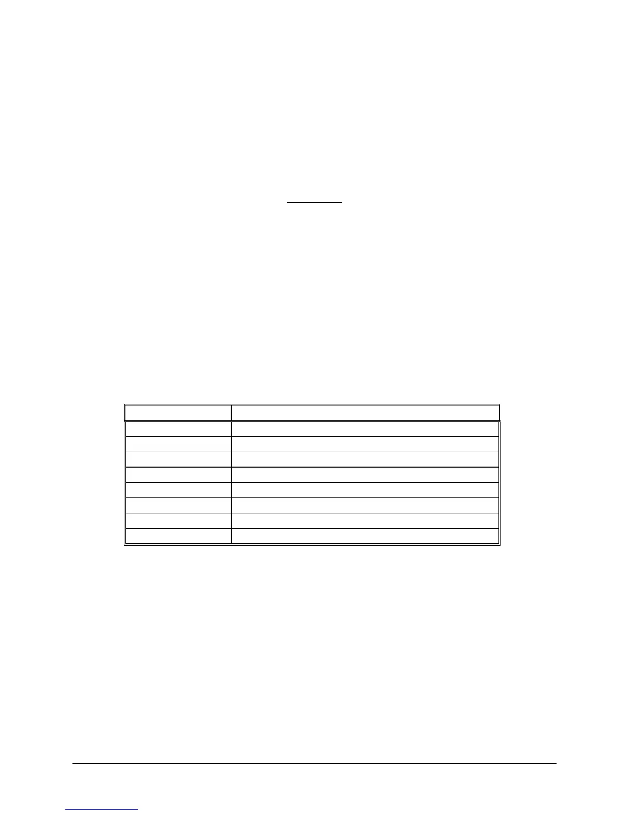
Table 4-1
Rear Panel BNC Connections
BNC Connector Signal
J4 Multi – Code DC Code Output
J5 Ext. Time Base Input or 10MHz Sine Wave Output
J6 Pulse/1PPS Input
J7 AGC Output
J8 Code Input
J10 IRIG B AC Code Output
J11 IRIG B DC Code Output
J12 Multi – Code AC Code Output
4-10 TM7000 TymMachine TCG/T (Rev D) Symmetricom, Inc.
 Loading...