CHAPTER FIVE
e. Insert the option assembly into the selected option slot, being careful that the
components are on the upper side of the assembly.
f. Reattach the Rear Panel Option Plate to the Chassis.
g. Attach any applicable I/O cables, and apply power to the unit.
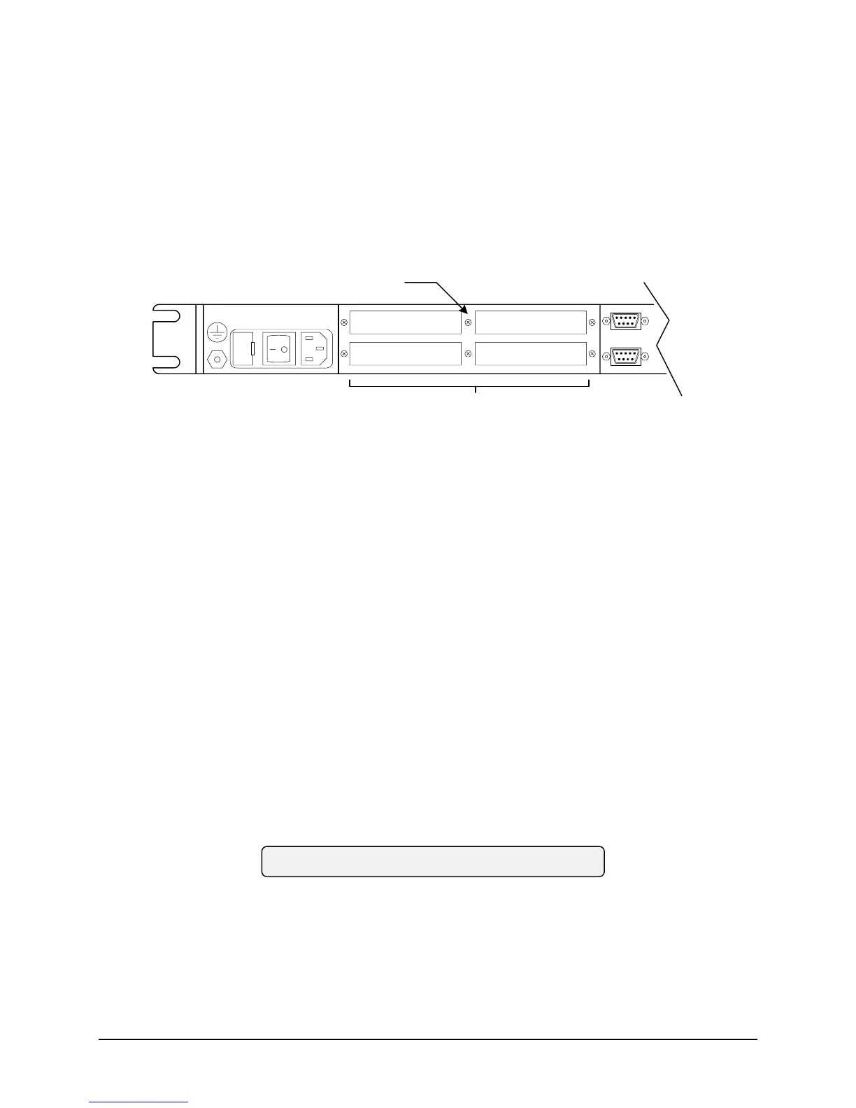
Figure 5-2
INPUT: 85-264VAC (47-440 Hz)
Fuse: 1.0A@100-120VAC 0.5A@220-
240VAC
J1
M1
M3
M2
M4
J9
J2
OPTION AREA
REAR PANEL OPTION PLATE
Replacement of a bolt-in module (STCG, Display Assembly etc.) can be easily accomplished
using the following procedure:
a. Removing power.
b. Remove the top cover.
c. Remove cables attached to the module
d. Remove the screws or nuts, which secure the module to the chassis.
Modules are replaced by reversing the above procedure. Take special care that all cables are
correctly connected, or the unit could be damaged.
5.5 ADJUSTMENTS AND TESTS
The following are adjustment and tests used to check adjustments if applicable. The adjustments
have been divided into two categories – Those that are routine adjustments, and those
adjustments that should only be performed if applicable circuit parts have been replaced.
The Top Cover of the TymMachine must be removed to make the following adjustments and
tests. This exposes a potential safety hazard in the Power Supply area which is located in the
right rear corner of the unit as viewed from the front.
*** CAUTION ***
5-8 TM7000 TymMachine TCG/T (Rev D) Symmetricom, Inc.
 Loading...