APPENDIX A
1.3 MAINTENANCE
No routine maintenance is required.
1.4 INTERCONNECTION
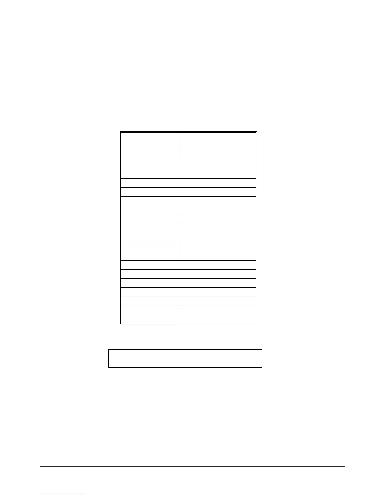
Connector pin out information For J1 is provided in Figures 2 and 3. J2, Auxiliary Outputs, are
shown in Table 2 below.
Table 2
J2 Auxiliary Outputs
20 Pin Flat Cable Type
Pin Number Function
1 Stop Pulse-Negative
2 Stop Pulse-Positive
3 GND
4 Stop Pulse-Positive
5 Stop Pulse-Negative
6 Interval DC
7 GND
8 Early N-C
9 Early C
10 Early N-O
11 Interval N-C
12 Interval C
13 Interval N-O
14
15 GND
16
17 GND
18
19 GND
20
REAR VIEW OF CARD-EDGE CONNECTOR
• 19 --------------------------------------------- 1 •
• 20 --------------------------------------------- 2 •
Figure1
See Figure 2, Tape Control Relays, for Tape Search Control Relay connections when using the
20138 assembly.
See Figures 2, Tape Control Relays and Figure 3, Tape Speed Relay connections when using the
20138-1 assembly.
Note: J1 is a 37 Pin D Male type connector.
A-2 TM7000 TymMachine TCG/T (Rev D) Symmetricom, Inc.
 Loading...