getting started
110
Synrad Firestar f-Series operator’s manual
Mounting
The Mounting section includes subsections:
■ f100/f200 mounting
■ f201/f400 mounting
Firestar’s baseplate is designed so that the laser is easily mounted using only three fasteners. On f100/f200
lasers, three ball bearing “feet” pressed into the baseplate eliminate any possible distortion of the laser
tube caused by variations in the atness of the surface on which the laser is mounted. On f201/f400 lasers,
a spherical cup and washer assembly positioned between the laser’s mounting brackets and the mounting
surface perform the task of eliminating tube distortion. Read through the mounting sections below to de-
termine which set of mounting holes are required for your application. When mounting Firestar lasers you
can choose to fasten from above, into your mounting surface, or from below, into the laser’s baseplate.
Caution
possible
equipment
damage
SYNRAD does not recommend mounting lasers in a vertical “head-
down” or “tail-down” orientation. If you must mount your laser in
this manner, please contact the factory for limitations as a vertical
orientation increases the risk of damage to the laser’s output optic.
f100/f200 mounting
Fastening f100/f200 lasers from above
To fasten your f100/f200 laser to a mounting surface from above, perform the following steps:
1
Determine whether you will use metric (ISO) or inch (SAE) fasteners to mount the laser. Three
1/4–20 UNC (SAE) capscrews are included in f100/f200 ship kits.
2
Refer to the appropriate outline and mounting drawing for dimensions and then drill and tap three
M6 × 1 or three 1/4–20 UNC holes into your mounting surface. These hole locations (referenced
by Note 1 on the O & M drawing) should correspond to the two slots labeled “A” and the thru hole
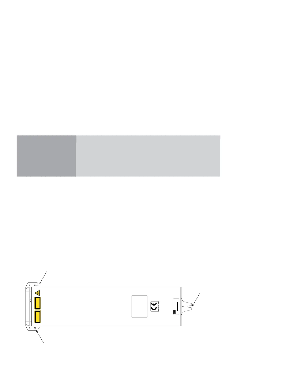
labeled “B” as shown in Figure 1-5.
Figure 1-5 Fastening f100/f200 from above
CAUTION
CONDENSATION AND
WATER DAMAGE CAN
OCCUR IF COOLING WATER
IS BELOW DEW POINT.
SEE OPERATION MANUAL.
EN-60825-1, 2007
400 WATTS MAX
10200-10800 NANOMETERS
INVISIBLE LASER RADIATION
AVOID EYE OR SKIN EXPOSURE TO
DIRECT OR SCATTERED RADIATION
CLASS 4 LASER PRODUCT
A
Cooling fittings
removed for clar
Top View
(f100 model shown)
The RF Drive circuit in this laser is designed to
sense fault conditions that could potentially
damage the laser’s electronic circuit boards.
On rare occasions, the laser may shutdown during
the start-up sequence. When this happens, the
Ready indicator will flash a series of three blinks,
pause, and then repeat. If this occurs, remove DC
power from the laser, wait 30 seconds, and then
re-apply DC power.
If the Ready indicator continues to flash, contact
SYNRAD, Inc. as this may indicate a serious
problem in the laser’s control circuit.
MODEL #: FSF100SD
SERIAL #: F100204082943
TESTED AT: 96V MFG: July 22, 2008
This laser component does not comply with standards for complete
laser products as specified by 21 CFR 1040.10 or IEC 60825-1.
SYNRAD, Inc. 4600 Campus Place, Mukilteo WA 98275 425.349.3500
 Loading...
